 |
|
|
|
|
| Max Ramp Weight |
|
| Max Taxi Weight |
|
| Max Takeoff Weight |
|
| Max Landing Weight |
|
| Max Zero Fuel Weight |
|
| Max Alt T.O. & LDG |
|
| Max Enroute Altitude |
|
| Min Temp T.O. & LDG |
|
| Max Temperature |
|
| Max Tailwind T.O/ LDG |
|
| Max Runway Slope |
|
| Max Fuel Imbalance |
|
Speeds
| Vmo/Mmo |
|
| Va |
|
| Vle / Vlo |
|
| Vsb |
|
| Vturb |
|
| Vfe |
|
|
|
|
|
|
|
| Load Factor |
|
|
|
|
| Max Engine Overspeed |
|
| Max Engine RPM / EGT |
|
| Min Oil Temp for Start |
|
| Min Oil Press @ 95% RPM |
|
| Max Oil Consumption |
|
| Max Occupants |
|
Minimum Brake Cooling Time
| Flap 15 Takeoff |
|
| Flap 0 Takeoff |
|
| After Abort |
|
| After 2 Aborts |
|
Note: If Takeoff Weight is to exceed 20,500 lbs, consult
the brake cooling chart section 4 page 19 of the AFM.
|
|
Do not use auto pilot below 200 kts Flaps Up as per section 2
page 15 of the AFM. Auto pilot altitude hold must remain disengaged
during severe turbulence. No auto pilot use above 15,000 ft at speeds less
than 155 kts or less than Vref + 20 kts below 15,000 ft. Auto
pilot must not be used below 1,300 ft except on a coupled ILS approach.
Coupled approach be flown to 240 ft AGL. When auto pilot is in use,
aft CG limit is 1% MAC forward of normal limit.
|
|
The Rolls Royce Viper engine powers all of the "Straight
Pipe" Hawker Jets. It was originally designed to power drones, and
be destroyed by some new weapon system in short order. It did, however,
turn out to be a very reliable engine, and was installed on the Hawker
Jet. One odd thing is that there was no provision to recover the
oil that is used to lubricate the aft engine bearing. This oil was
discharged into the jet exhaust, and never seen or heard from again.
To this day, this is still true. You must service the engine oil
almost each flight. Other than this, it was really a good engine
in it's day.
The Viper Engine has a "Top Temp Limiting" device
that limits fuel flow such that you do not exceed the maximum engine exhaust
gas temperature during takeoff, or during climb, as you select on the three
position switch that controls the system. You have "Takeoff", "Climb",
and "Off" positions.
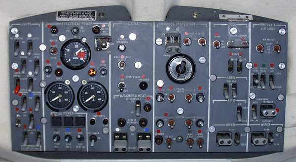
On the old Hawkers, you must make sure that the
correct engine start mode is selected, or the engines will not crank.
GPU starts are made with the switch in "Norm", and battery starts are made
with the switch in "Internal". If one of these two does not work,
check the voltage on your 3rd battery! It is used to power the start
relay. No # 3 Batery, no engine start!
Some of the 1a airplanes have been fitted with the
TFE-731 engine. This makes for a stage 3 airplane as far as noise
goes, and extends the range quite a bit. A 1a fan will burn about
1800 lbs the first hour and 1400 lbs thereafter. It will go about
4.5 hours at a little over 400 knots.
|
|
|
|
|
|
The HS-125 carries its fuel in the wings, and on most of the
newer models, in a verteral tank. The 1A model has wing tanks only.
The fuel is supplied to the engine driven fuel pumps by an electric boost
pump located in each wing tank. Two valves are installed between
the respective sides of the fuel system. The "Crossfeed " valve allows
feeding of one engine from the opposite tank, and feeding both engines
from a single tank. The "Interconnect" valve allows transfer from
one tank to another.
To "Crossfeed", place the fuel Crossfeed / Transfer lever to
the first detent. This opens the crossfeed valve. Leave the
boost pump ON in the tank you wish to feed from. Turn the opposite
boost pump off. The operating boost pump provides fuel to any engines
that are running.
To "Transfer" fuel, place the fuel Crossfeed / Transfer lever
to the "Interconnect" position. This opens both the crossfeed and
transfer valves. Leave the boost pump on in the tank you wish to
transfer TO! Turn off the pump on the side from which you wish to
extract the fuel. Remember, always open the valves prior to turning
off any pumps, and turn on all pumps before closing any valves.
|
|
Methyl alcohol is provided to de-ice the fuel filters. This
alcohol is pumped from a reservoir located on the side of the fuselage
at the trailing edge of the right wing under the engine nacelle.
Use fuel filter de-ice any time you get a fuel filter clogging light.
Just prior to descent, use 3 seconds of fuel filter de-ice, then switch
to "Auto" for the remainder of the descent. Some like to just set
the switch to "Auto" for the duration of the flight. I prefer not
to do this, as you may run out of fluid and not know it until its too
late. My recommendation is to leave it off during climb and cruise,
give it about a 5 second blast at top of descent, then "Auto" for the descent.
This way a malfunction should not rob you of your engines due to ice clogging
the fuel filter. These recommendations are as a result of experience
with the airplane.
|
|
 |
|
|
The HS-125 is equipped with two starter generators, two main batteries, and a third battery. The main batteries provide emergency power in the event both generators are lost, and give you internal start capability. The third battery has the sole duty of operating the start relays. This prevents the start relay from opening and closing during engine cranking due to a drop in battery voltage. If the third battery is dead, the engines wont start, even with a GPU, as the start relay will not close. The loss of one generator will not cause loss of any equipment, as the "Bus Tie" relay will close, indicated by illumination of the amber Bus Tie light.
Viper Powered Aircraft
| Ground Operation | 110 Amps 5 Min |
| 80 Amps Cont | |
| Flight | 235 Amps Max |
|
|
Main
The main hydraulic system on the HS-125 uses 5606 fluid.
It operates the landing gear, brakes, flaps, airbrakes, lift dump, and
nosewheel steering systems. There is an emergency system that may be used
to lower the landing gear, and operate the wing flap system.
The main system has an engine driven pump on each engine, and a hydraulic reservoir in the tailcone. There are cockpit indicators that tell you if each hydraulic pump is operating. They are mechanical, and will read "NORM" or "FAIL" depending upon the output flow of the respective hydraulic pump. The main system is used to charge the brake accumulator to provide a parking brake, and emergency braking if the main hydraulic system fails, or is just not operating, such as on the ground prior to engine start. This system may be charged by a hand pump located in the tail of the airplane. This is not to be confused with the "Emergency " system. The hand pump in the tail provides pressure to the main system, but at a lower rate than the engine driven pumps, unless you are Charles Atlas on steroids! The hand pump in the cockpit operates the emergency system only.
Emergency
The emergency hydraulic system will lower the landing gear, and
operate the wing flaps. To activate the system, place the gear switch
down, pull the emergency gear extension handle on the left side of the
throttle quadrant, and pump. The gear will come down slowly, as you
operate the hand pump. To operate the flaps, merely select the flap
position you desire, and operate the hand pump until the flaps reach that
position. The flaps may be raised or lowered, however the landing
gear may only be extended with the emergency system. The emergency
system reservoir is in the nosewheel well. It is depleted when the
emergency system is used, so if you pump the flaps to check the system,
have maintenance check and possibly service the emergency reservoir.
|
|
The ailerons and elevator and rudder on the HS-125 are manually actuated by the pilots. The aircraft does have an autopilot. The ailerons and elevator may be moved by the autopilot servos, and the rudder is equipped with a yaw damper, and a rudder bias system.
Rudder Bias
Flaps
Airbrake
Lift Dump
Nosewheel Steering
Brakes
|
|
At 21,200 lbs Flaps 15
| Sea Level 15 Deg C | 4,700 ft Runway Required |
| 20 Deg C | 5,200 ft Runway Required |
|
|
Climb Limited @ 15 deg Flap |
Stall Speeds
| Vs @ 15,000 lbs | |
| Flap 0 Deg |
|
| Flap 15 Deg |
|
| Flap 25 Deg |
|
| Flap 50 Deg |
|
These stall speeds increase 3 kts per 1,000 lbs above 15,000 lbs. So at 20,000 lbs, the 1 G flaps up stall speed is (5 x 3)+(91) = 106 kts. This is accurate to within about one knot.