 |
|
|
|
|
| Lear |
|
| Max Ramp Weight
35-345 & Sub with ECR 2234 36-002 to 045 with AAK 80-2 36-046 & Sub |
|
| Max Ramp Weight
36-002 to 045 without AAK 80-2 |
|
| Max Takeoff Weight
35-067 to 344 with AAK 80-2 35-345 & Sub with ECR 2234 36-002 to 017 with AAK 76-4 and AAK 80-2 36-046 & Sub |
|
| Max Takeoff Weight
35-067 & Sub with AAK 77-8 35-001 to 344 with ECR 1495 36-002 to 045 without AAK 80-2 |
|
| Max Landing Weight
35-356 & Sub 36-002 to 046 with AAK 80-3 36-047 & Sub |
|
| Max Landing Weight
36-002 to 046 with AAK 80-3 |
|
| Max Wing Bending Weight ( no restrictions )
Xfer prior to Total wing fuel = 2250 lbs If Xfer fails, Vmo = 325 kts |
---- 14,000 lbs |
| Max Baggage Comp. |
|
| Typical Empty Weight |
|
* All weight in excess of the Max ZFW must be fuel in the Wing and tip tanks.
The above weights are maximum certificated limits. The actual maximum weights for a particular flight may vary a great deal due to performance limitations. If the aircraft can not meet the required "Takeoff Field Length" and "Climb" limitations, (engine out climb performance), the maximum takeoff and/or landing weights are reduced such that the requirements are met. See the performance charts in the AFM for details.
Speeds
|
|
|
| Vmo
|
359 kts |
| Mmo
|
0.74 M 0.74 M |
| Va |
|
| Vfe 8 Deg
20 Deg 40 Deg |
183 kts 153 kts |
| Vlo
Vle |
260 kts |
| Vsb
(Not with flaps when airborne) |
|
| Vmca
Vmcg |
103 kts |
| Nosewheel Steering
Primary Wheel Master |
Authority 45 kts |
| Max Tire Groundspeed |
|
Yaw Damper Off for T.O., On for Flight, Optional for LDG
Airplane shall be configured for landing by 500 ft AGL
Lear Jet
|
|
|
| Max Alt T.O. & LDG |
|
| Max Enroute Altitude |
|
| Max Cabin Pressure
Relief |
10.0 psi |
| Min Temp T.O. & LDG
Max Runway Clutter |
|
| Max Tailwind T.O/ LDG
Max X-Wind Takeoff / Land |
24.7 kts |
| Max Runway Slope |
|
| Max Fuel Imbalance |
|
| Max Tip Fuel / Landing |
|
| Load Factor Limit
Flaps Up Flaps Extended |
2.00 G |
Engine Limitations
Note: Idle for 3 Minutes prior to takeoff if ambient temp is below
- 25 C
See AFM for Approved oils. Do not mix brands of oil.
Engine Limitations
Lear 35 / 36
|
|
N1 | N2 |
|
|
|
|
|
|
870 C |
10 Sec |
|
|
|
|
870 C |
5 Seconds |
|
|
|
|
|
|
|
|
|
|
|
|
|
Max Transient |
105.0 % |
105.0 % |
---- |
5 Seconds |
|
|
|
| Max Oil Temp
Max Cont. Min Normal |
127 C 30 C |
| Min Oil Temp for Start |
|
| Max oil consumption / 25 hours |
|
| Max Oil Press |
|
| Min Oil Press |
|
| Normal Oil Press |
|
Systems
|
|
Primary Flight Controls
The ailerons, elevator and rudder on the Lear Jet
are manually actuated by the pilots. Aileron and rudder trim is achieved
with trim tabs on the rudder, and left aileron. These trim tabs are
positioned by electric motors located inside the left aileron and the rudder
it's self. Pitch trim is achieved by changing the position of the
moveable horizontal stabilizer. There are two trim motors that will
do this, a primary, and a secondary. The aileron, rudder,
and primary pitch trim are controlled with a thumb switch on the left side
of the Capt.'s and right side of the Co-Pilot's control yoke. The
secondary trim is actuated by the autopilot, and can be controlled by an
electric switch on the console in the event the primary trim fails.
The aircraft does have an autopilot, although not
a very good one until you get to the 31, 45, 55 or 60. The ailerons
and elevator may be moved by the autopilot servos, and the rudder is equipped
with a primary and secondary yaw damper. Both yaw dampers are required
for flight although only one may be engaged at a time.
The Lear Jet has two stall warning systems.
They are the same. Both are required for flight. Angle of attack
information is given to the system by two angle of attack vanes located
on the left and right sides of the nose of the aircraft. These vanes
are heated when the pitot heat switch is on. They get hot enough
to burn you, so touch them with caution.
About 7% above a stall, the system warns you with
a flashing stall warning annunciator light, and by activating the stick
shaker. At about 5% above a stall, the autopilot pitch servo applies
an 80 pound push on the elevator. If you do not notice this, you
deserve to crash! It is hard to ignore.
There is a "Wheel Master" button just below the
trim actuator on each pilot's yoke. It is a handy little guy.
It interrupts any elevator trim action, deactivates the stick pusher, disengages
the autopilot, and will engage the nosewheel steering if the gear is down.
The trim check very important on the Lear Jet, as the trim system on this aircraft, if not properly set can KILL you within seconds after liftoff. Excuse the lack of tact here, but it's a fact. Perform the trim check prior to takeoff.
Flaps
The flaps on the Lear are hydraulically actuated.
The flaps are controlled in one of two ways, depending on the model lear.
Most have one switch with three positions, Extend, retract, and off.
Select extend, or retract until the flaps are in the desired position,
then select off. Some Lears have preselect where you place a lever
in the desired flap position, and the flaps extend to the position requested.
If the flaps will not extend, add 30 kts to your approach speed and 30%
to your landing distance.
There is pressure relief valve in the flap system
that will prevent damage to the flaps if they are inadvertently extended
or left down at speeds in excess of their operating limitations.
Spoilers
Lear Jets are equipped with spoilers. They
may be deployed up to Vmo / Mmo in flight only when the flaps are retracted.
On landing, they should be deployed just after touchdown. They are
hydraulically actuated, and electrically controlled. They have two
positions, fully deployed, and stowed.
Spoilerons
The Lear 30 and later models are equipped with spoilerons.
They may be deployed up to Vmo / Mmo in flight only when the flaps are
retracted. On landing, they should be deployed just after touchdown.
They are hydraulically actuated, and electrically controlled. They
have two positions, fully deployed, and stowed.
When the flaps are more than 25 deg extended, the
spoilers will extend on one side or the other to provide better roll control
at approach and landing speeds. The spoiler on the same side as whatever
aileron is deflected upward will match the position of that aileron.
This kills some of the lift on that side, and makes low speed roll control
much more effective than on the 20 series airplanes. This feature
requires AC power to function.
Nosewheel Steering
The nosewheel steering on the Lear is electric.
It requires both AC and DC to operate. Steering is engaged with the
wheel master switch, or by a "Steer Lock" switch on the left side of the
Capt.'s panel on 20 series airplanes, and the center pedestal on 30 series
and later models. Maximum speeds for use of nosewheel steering is
either 45 knots, or 10 knots, depending on the steering mode selected,
and / or loss of wheel speed input from more than one of the right three
main wheels. See AFM for details.
Landing Gear
Like all other aircraft intended for more than one
flight, the Lear jet has a landing gear. It is extended and retracted
hydraulically, and controlled electrically. It can be extended with
high pressure nitrogen if the normal extension fails.
Brakes
Each main landing gear on the Lear Jet has
two wheels and tires. Each wheel has it's own hydraulic brake, with
anti-skid protection. The brakes on the left gear are controlled
by pressure applied to either of the left brake pedals, and the right brakes
work the same way from the right pedal pressure. The anti-skid system
can relieve the brake pressure on any individual wheel.
If the hydraulic brake system fails, there is an
alternate brake system that will apply the brakes with high pressure nitrogen.
The same bottle is used for emergency gear extension. The emergency
brake system does not provide any anti-skid, or differential braking capability.
It is a good system, and if you use it with your brain engaged, it works
fine.
** Prior to takeoff, ALWAYS check the 3 Killer Items **
|
|
|
|
Fuel Capacity
|
|
|
|
|
|
|
|
|
0.77 Mach / 440 kts |
|
|
| Fuel Type |
|
|
| Jet A / Jp-5 |
|
|
| Kerosene |
|
|
| Jet B / Jp-4 |
|
|
| Avgas |
|
15,000 ft & 25 hr max |
Note:
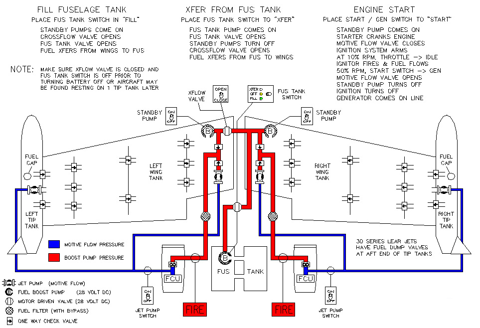
This section describes the basic fuel system on
Lear Jets. The 28 and 31 models have no tip tanks, but are otherwise
about the same, and the 23 has a different crossflow arrangement, and fills
the fuselage from the left wing tank only. The 36 models have a means
to fuel the fuselage tank with a fuel hose, and to gravity transfer all
but about 400 lbs of the fuselage fuel without the fuselage pump.
Otherwise all 20 thru 50 series Lear have basically the same fuel system.
|
|
|
|
|
|
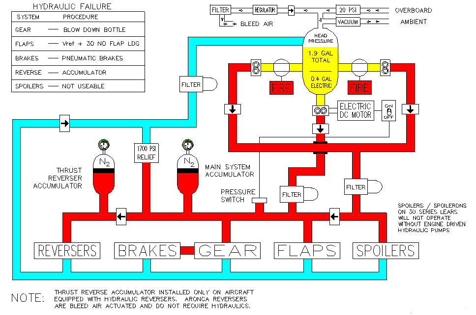
The Lear Jet hydraulic system consist of 2
engine driven, and one electric hydraulic pump, a 1.9 gallon reservoir,
an accumulator (two accumulators if Dee Howard reversers are installed)
and a couple of pressure relief valves. The fluid is 5606 therefore
if you spill some on yourself, you won't wind up looking like you and Michael
Jackson share the same dermatologist. The system operates the landing
gear, normal braking with anti-skid, the flaps, spoilers, and thrust reversers
(except aeronca) if the aircraft is so equipped.
The reservoir is pressurized by bleed air on later
models, and cabin air on earlier Lears. This is to prevent foaming.
The engine driven hydraulic pumps can only access 1.5 of the 1.9 gallons
of hydraulic fluid. The additional 0.4 gallons can be used by the
electric hydraulic pump only. It can extend the landing gear, the
flaps, provide normal braking with anti-skid, and on the 20 seriesonly,
extend the spoilers. The hydraulic thrust reversers have their own
accumulator, and should be useable even with total hydraulic failure.
The system has two pressure relief valves, one main
system relief valve, that relieves at 1700 to 1750 psi, and one relief
valve in the flap system that relieves about 1650 psi. See "Flaps'
in the flight controls section for more details on this.
With total hydraulic system failure, blow the gear
down, approach at Vref + 30 kts, use pneumatic brakes, and plan on 1.7
to 2.0 times your normal landing distance. T/R's may work!
 |
|
|
|
|
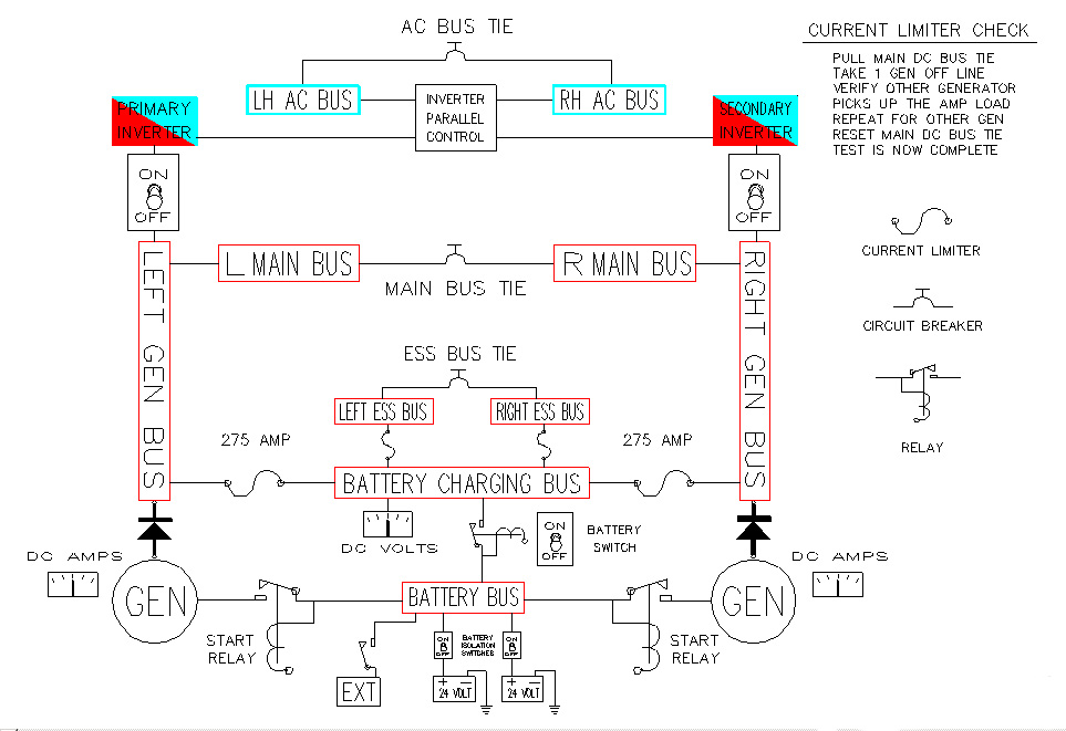
"DC" Electrical
The Lear Jet 30 series DC electrical system is only slightly more complex than the earlier models. It consists of: Two batteries, usually one, but sometimes two standby batteries, two starters, two generators, several busses, some relays, current limiters, quite a few circuit breakers, and two battery switches. The main difference between the 30 series (and some later 25's) is the added "Essential" busses. They are busses that can still receive battery power with both current limiters blown.
The current limiters connect the generators to the battery
bus. The starting current goes through the start relay, and does
not pass through the current limiter. The current that recharges
the batteries does. If you blow a current limiter other than due
do an electrical short, it will probably be just after engine start when
you put the first generator online. Because the batteries are in
a discharged state, they want all of the electrons they can eat.
This is sometimes more than the current limiters can take.
 |
|
|
|
|
|
| Generators
Flight |
400 Amps |
| Batteries 1 & 2
Battery 3 |
24 Volt / 04 Amp Hour |
Standby Battery
The standby battery switch has three positions: OFF, STANDBY, and ON. In the ON position the emergency battery powers the small third attitude indicator, it's light, and the control circuits for the landing gear and flap systems. The three green landing gear lights are also powered by the emergency battery, and will illuminate when the gear is down and locked. The red "gear door not locked" lights are not powered by this battery. In standby, it powers just the gyro and it's light. Most of these batteries will charge in the ON and Standby positions, however, some, such as the ones in the Lear 28 must be left "ON" to be charged. Some later model aircraft may be equipped with a second standby battery. This will usually power an emergency comm radio, and whatever other devices the customer would like.
If you experience loss of all main DC bus power for any reason, remember the following:
1. Emergency battery switch to ON. Landing gear extension
will be normal
except for the loss of the red gear
door warning lights.
2. Landing gear warning horn will be inop.
3. Engine stator and nacelle lip heat are on.
4. Wing and tail anti-ice, pitot static, and angle of attack
probe heat will be inop.
5. Windshield Heat will fail in the last position selected.
6. Tank to tank fuel transfer will not be possible if crossflow
valve
was closed at time of power loss.
If crossflow valve was open, the
boost pumps will fail, making
pressure fuel transfer impossible, however,
the crossflow valve will remain
open, allowing some fuel transfer due to a
very reliable power source called
gravity.
7. The AC electrical system will be inop as it receives
it's power from the DC system.
8. The hydraulic system will be inop, except for the landing
gear and flaps, as their
control circuitry is powered by
the emergency battery when the "ON" position
is selected.
9. Nosewheel steering will be inop, as it requires
both AC and DC electrical power.
10. Anti-Skid system is inop.
These things may require some thought as to how one wishes to conduct the remainder of a flight.
Normal Operation:
Battery switches ON, before engine start,
all DC busses are powered by batteries or GPU. After engine start,
all busses are powered by the generator(s), and the batteries are recharged.
Battery Overheat
Respective battery switch OFF. This prevents
battery charging. DC busses powered by generator(s). Monitor
temp of offending battery. If your lear does not have dual battery
switches, use the battery disconnect switch for the offending battery.
All 30 series and later Lears have dual battery switches.
"AC" Electrical System
A Lear Jet is usually equipped with two inverters.
A third inverter is an option on Lear 24's and all later Lear Jets.
Almost all of the Lear 30 series are equipped with two solid state inverters.
Either one can supply AC power to all items on the aircraft that require
it. They normally operate in parallel, but if one fails, the other
picks up the remaining load automatically. An AC paralleling unit
aligns the phase of the two inverters to make them work in parallel.
The AC items on the Lear include: Gyros, Autopilot,
Altitude Alert, Mach trim system, Nosewheel Steering, Engine pressure gauges,
and a few other items that vary from aircraft to aircraft.
|
|
Lear Jets of the 30 series and later are all certified
for flight into known or forecast icing conditions. Starting from
the front of the airplane, the radome is anti-iced by alcohol that is pumped
onto it through a plastic nozzle located at the very front of the airplane.
The same alcohol pump provides emergency anti-ice for the left windshield.
You have about 90 minutes for the radome, and 45 minutes for the radome
and windshield together.
The pitot tubes, static ports, and angle of attack
vanes are electrically heated, controlled by the "Pitot Heat" switches
in the cockpit. The windshields are heated with engine bleed air.
The wing and horizontal stab leading edges are heated by bleed air.
Engine nacelles and stators are heated by bleed
air. The bullet shaped nose cone for the 731 engine was heated with
bleed air as well, however almost all of the airplanes have been fitted
with the conical spinners, and require no heat, as their shape and rotation
does not allow large enough amounts of ice to form to pose any hazard to
the engine.
|
|
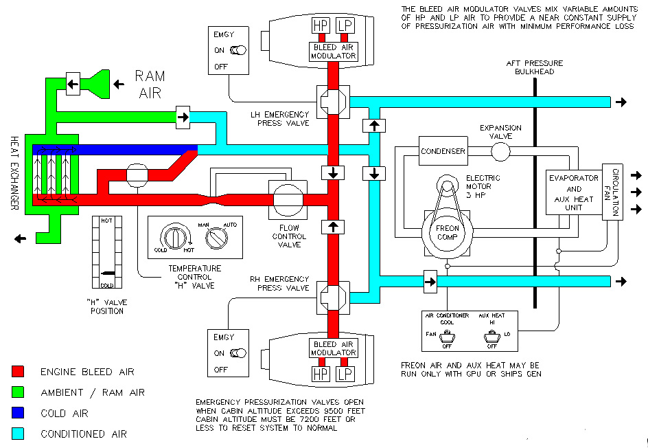
The Lear 35 / 36 is pressurized, like most airplanes,
by engine bleed air. This air comes from the HP and LP bleed sources
on the engine through a "BSV" (bleed switching valve) that regulates the
bleed air pressure by controlling the mix of LP and HP air. This
air goes through a heat exchanger in the tailcone of the airplane, and
is cooled, then goes into the cabin. Temperature is regulated by
a "Damper Valve". This valve controlls the ambient airflow across
the non pressurized side of the heat exchanger. This does not
provide enough cooling for low altitude and hot weather, so a freon airconditioner
is provided for use below 18,000 feet.
Emergency pressurization air is provided by way
of the windshield heat system. Place the defog knob so the windshield
air goes to the inside of the airplane, and you have another source of
air for pressurization. The newer models have two emergency bleed
valves that will automatically open when the cabin altitude exceeds about
9,500 feet. These valves allow uncooled bleed air to pressurize the
cabin.
On the outflow side of things, the cabin pressure
is regulated by a main outflow valve, located at the forward end of the
pressure vessel. The automatic pressurization system requires AC
power. In the event the automatic pressurization fails, cabin pressure
may be controlled pneumatically, by the "Cherry Picker" that uses air to
move the outflow valve. Maximum differential relief between
9.3 and 10 psi, and negative pressure relief at - 0.25 psi, and positive
pressure depending on the model and serial number airplane. This
"Safety outflow valve" is strictly mechanical. It requires no electrical
power.
 |
|
|
|
|
Here are some basic flight profiles that I have used over the years. They are not the only way to fly the airplane, but have worked for me since I started giving training and checkrides in the Lear a little over 20 years ago. In the event of a difference between this and the Aircraft Flight Manual, the flight manual is the document to follow.
Steep Turns
1. Enter at 250 KTS indicated AIRSPEED.
2. Bank aircraft 45 deg. As passing 30 deg bank,
pitch up 2 deg. Add power to maintain speed.
3. Lead roll out by 15 deg. Passing 30 deg bank, pitch
down 2 deg to maintain altitude.
4. Maintain 250 KTS and assigned heading.
Stall - Cruise Configuration
1. Compute Vref & set AIRSPEED bugs.
2. Maintain assigned altitude and set power to 50%
N1.
3. Trim for level flight until passing 150 KTS.
Maintain altitude with necessary back pressure.
4. At stick shaker or stall warning lights,
throttles to " MAX POWER "
5. Call " MAX POWER Flaps Approach.
6 Reduce pitch ONLY to the extent necessary
to eliminate symptoms of the stall.
7. Reestablish assigned altitude.
8. At Vref + 30 KTS, call " Flaps Up, After Takeoff
Checklist. "
9. Maintain AIRSPEED and altitude as directed.
Stall - Takeoff Configuration
1. Compute Vref, set AIRSPEED bugs & select flaps 20.
2. Maintain assigned altitude and set power to 50% N1.
3. Trim for level flight until passing 150 KTS.
4. Maintain altitude with necessary back pressure.
5. At stick shaker or stall lights, advance throttles & call
" MAX POWER ".
6. Reduce pitch ONLY to the extent necessary to eliminate symptoms
of the stall.
7. Reestablish assigned altitude.
8. At Vref + 30 KTS, call " Flaps Up, After Takeoff Checklist.
"
9. Maintain AIRSPEED and altitude as directed.
Stall - Landing Configuration
1. Slow to flap speed, set 60% N1 & Set bug to Vref.
2. Maintain assigned heading & altitude.
3. Below 198 KTS, " Flaps 8 deg".
4. Below 183 KTS, " Flaps 20 deg ".
4. Gear Down, perform Landing Check
5. Below 150 KTS, " Full flaps. " trim to Vref. Establish
a 400-700 feet/min sink rate at Vref.
6. Level off at designated altitude W I T H O U
T increase in power
7. Maintain altitude until first indication of a
stall. (Shaker or stall lights)
8. Apply MAX power lower nose only as much as required
to eliminate the stall warning.
At Vref minus 10 KTS
M I N I M U M speed, call for " Flaps 20 deg", and increase the
pitch attitude to 10 deg nose
up at about 1 deg / sec.
9. When VSI & Altimeter indicate positive rate of
climb call " Positive rate, Gear Up ".
10. Establish 7.5 deg nose up attitude.
11. At Vref + 30 KTS, Call " Flaps Up, After Takeoff Checklist
".
12. Return to entry heading and altitude or as directed.
ILS Approach - Two Engines
1. Intercept LOC at 140-160 KTS and Flaps 20 deg.
2. One dot prior to intercepting Glide Slope, call " Gear Down
Landing Check ".
3. When ON the glidepath, call " Full Flaps ".
4. Establish Vref to Vref + 5 KTS & track LOC & GS until
Minimums.
ILS Approach - One Engine
1. Intercept LOC at 140-160 KTS and Flaps 8 deg.
2. One dot prior to intercepting Glide Slope, call " Gear
Down Landing Check ".
3. When ON the glidepath, call "Flaps 20 deg".
4. Establish Vref + 20 KTS & track LOC & GS
5. At 100-150 Ft AGL, Full flaps, power idle & land.
Non Precision Approach - One or Two Engines
1. Intercept Final Approach Course at 140 KTS and
Flaps 20 deg.
2. Crossing Final Approach Fix, call " Gear Down
Landing Check ".
3. Descend to and maintain MDA until Field in Sight
or MAP is initiated. ( As Appropriate ).
4. If Landing is to be made, call " Full Flaps "
when intercepting a glidepath appropriate for a
normal landing. For one
engine INOP, Vref + 20 KTS until 100 feet AGL, then " Full
Flaps" so as to descend thru 50
ft AGL at Vref as in a normal landing.
No Flap Approach
1. Vref + 40 KTS until established on Final Approach.
2. Vref + 30 KTS on final.
3. Approach angle NORMAL. A flat approach will usually
result in a longer landing roll.
Go Around or Missed Approach
1. "Max Power", Rotate to 10 deg, " Flaps 20 deg".
2. Positive Rate of Climb, " Gear Up ", Vref + 30, " Flaps up,
After Takeoff Checklist ".
3. Climb at 200 KTS.
4. Engine Failure or Fire Checklist if Appropriate.
Takeoff
1. Set V2 on Capt. Airspeed & V1 on Co-Pilots Airspeed.
2. At V 1, BOTH hands on Yoke.
3. Vr, Rotate to 15 deg ( 2 eng ) 12 deg ( 1 eng ).
4. Climb at 15 deg pitch, ( 2 eng ) or V 2 ( 1 eng ).
5. At 400 ft & V2+30 KTS, "Flaps Up After T.O. Check ".
6. Engine Failure or Fire Checklist if Appropriate.
7. Climb 200 KTS to 3000 AGL then 250 Kts.
Rejected Takeoff
1. Proceed as in normal takeoff until malfunction dictates that
the takeoff be rejected.
2. Capt. calls "Abort" (Co-Pilot may call Abort if Capt elects
to delegate that authority).
3. Thrust levers to idle
4. Spoilers extend.
5. Wheel brakes as necessary.
6. Thrust Reverse OR Dragchute deploy. (Never Both at the
same time!!)
7. If another takeoff is contemplated consider brake energy &
appropriate turnaround time.
Emergency Descent
1. Oxygen masks on within 5 sec of cabin pressure
loss.
2. Check passenger oxygen masks deployed.
3. Select Oxygen mask microphone.
4. Ignition ON.
5. Thrust levers to idle.
6. Spoilers and Landing Gear, Extend.
7. Auto Pilot OFF.
8. Initiate 45 deg bank if desired.
9. Vmo/Mmo minus 10 kts to 14,000 or MEA as
required.
10. Clean up & proceed to nearest suitable airport if appropriate.
Condition of aircraft or
reduced range due to low
altitude may make flight to original destination unwise.
Back to: Airplane Driver's Network