|
|
PERFORMANCE: FAR PART 25
FAR parts 23 and 25 specify criteria that airplanes must meet to obtain certification. These regulations contain many standards relating to materials, construction, performance, flight characteristics, and more.
In a normal category airplane such as a light twin, the regulations do not require that the aircraft be able to climb, or even maintain altitude if an engine failure occurs during the departure. In fact, if the failure occurs between rotation and Vyse, you may find yourself unable to stop on the runway, AND unable to continue. The result will likely be a controlled crash.
Transport Category aircraft, if operated within their limitations, never depart at a gross weight such that the failure of one engine will leave the pilot without the performance capability to either stop on the remaining runway, or continue the takeoff with the remaining engine(s). Similar weight limitations exist for landing. If operated at legal weights, the part 25 aircraft can always execute a go around or missed approach with an inoperative Powerplant.
Transport Category aircraft have two sets of weight limitations. "Certificate Limitations" such as Maximum Takeoff or Landing weight, and "Performance Limitations" such as Maximum Takeoff Weight permitted by climb requirements, or Runway Limited Takeoff Weight. Compliance with BOTH limits is mandatory. The certificate limits remain constant, but the performance limits vary as the altitude, temperature, runway and wind change. A hot day, high elevation or short runway can limit your Max Takeoff Weight to a figure well below the Max Certificated Takeoff Weight. Remember, in FAR part 25 (Transport Category) aircraft, performance limits are OPERATING LIMITATIONS, not just "Good Information".
There are some terms and definitions one must know if the FAR part 25
performance data presented in most Flight Manuals is to be understood.
We will define them now.
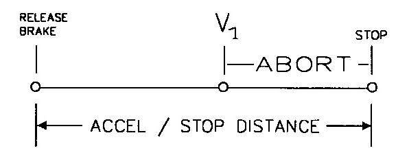
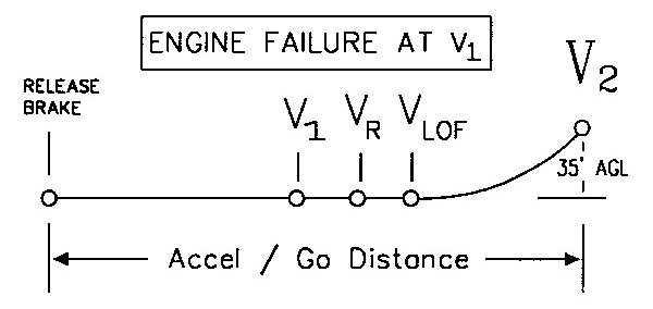
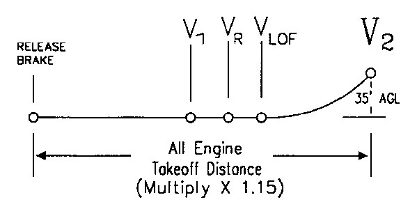
Balanced Field Length
The distance required to accelerate to V1, and stop; or accelerate to V1, lose an engine, and reach a speed of V2 at an altitude of 35 ft AGL, or at least 115% of the distance required to reach V2 and 35 ft AGL with all engines operating, whichever is greater. If the accelerate stop distance and accelerate go distances differ, the longest distance will be used. The term Takeoff Field Length would be used to describe the required takeoff distance in this case.
Gradient
A gradient is a means of answering the question "How steep is it?" Gradients
can be expressed in terms of "percent". During a drive through the mountains
we will likely see a sign that says " 6% Grade next 5 miles Trucks use
low gears". A gradient is the ratio between a horizontal distance and a
vertical distance. Hills with a 6% grade will change elevation six feet
for every 100 feet of horizontal distance traveled.
CLIMB SEGMENTS
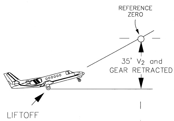
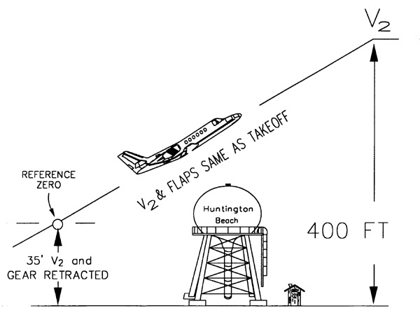
First Segment
This segment begins liftoff and ends when gear retraction is complete and you are at least 35 feet AGL and have attained a speed of V2. The first segment is generally not the one that is limiting.
|
|
|
|
|
|
|
|
|
|
|
|
|
|
|
|
|
|
Second Segment:
This segment begins at the end of the first segment and ends at a minimum height of 400' above the runway. This is the always the most restrictive climb segment for all two engine jets currently certificated. It may not be the most limiting for some older airplanes who's engines have a substantial difference between Take-Off, and Maximum Continuous power. One example of this is the Jetstar -6. The engines have 3,000 lbs thrust for takeoff, and 2,575 lbs at maximum continuous. The power reduction at the end of the third segment results in a substantial reduction of thrust. In this case, the 4th or final segment climb can be the one that is limiting. If your aircraft has a chart like "Maximum Takeoff Weight Permitted by Climb Requirements", you need not know which of the segments is actually limiting.
|
|
|
|
|
|
|
|
|
|
|
|
|
|
|
|
|
|
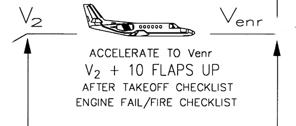
Third Segment:
This segment extends from the end of the second segment to the completion of flap retraction and acceleration to Venr. Meeting the 3rd segment requirements means that you can start at V2 and flaps takeoff, and accelerate to Venr or Vfs, retracting the flaps during the appropriate part of the acceleration, all without any loss of altitude.
|
|
|
|
|
|
|
|
|
|
|
|
|
|
|
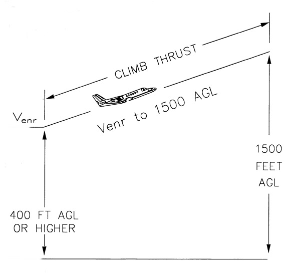
Fourth Segment:
This segment begins at the end of the third segment (flaps retracted), and ends at a height of 1500 feet AGL. This segment completes the takeoff path.
|
|
|
|
|
|
|
|
|
|
|
|
|
|
|
Balked Landing Climb:
This segment begins when an all engine go around is initiated and
the engines have reached go around thrust.
|
|
|
|
|
|
|
|
|
|
|
|
Approach Climb:
This segment begins when the gear is retracted, flaps are in the
approach position, one engine windmilling and the remaining engine(s) at
go around thrust.
|
|
|
|
|
|
|
|
|
|
|
|
 |
As we learned in our old high school science classes "Energy can't be created or destroyed, only changed." Mankind has built many machines that "change" energy from one form to another to suit our needs. Take for instance the automobile. Chemical energy within the gasoline is changed to heat, causing expansion of gasses within the engine. The energy in these expanding gasses is converted to mechanical energy used to turn the engine's crankshaft. Through the use of gears, this energy is finally used to make the car go. When the car is in motion it has what is called "kinetic energy". When you need to stop the car, you must convert this kinetic energy into another type of energy so the car will stop. We use devices called "brakes" to do this. The brakes convert the kinetic energy into heat. This heat will be absorbed by the atmosphere as the brakes cool.
The brakes can only handle a certain amount of heat. If they are forced to exceed this limit they may be damaged, and the intense heat generated may damage other nearby equipment.
If the brakes convert too much kinetic energy into heat in the process of stopping the airplane, they will heat the wheels and tires. If the wheel & tire assembly gets to hot, they could catch fire, or worse yet the tire could explode. The tires used by large aircraft are usually inflated to pressures in the 100 - 200 PSI range. This can make for a bang large enough to seriously damage an airplane and possibly really bugger up your day..
In order to avoid this, "fuse plugs" are installed in the wheels. The cores in these fuse plugs will melt and release the pressure within the tires prior to the tire failing or catching fire due to the heat. It is far better to have a flat tire during taxi or parking than to risk an explosion. The best way to deal with all this is to check the Aircraft Flight Manual for brake energy limitations and do not exceed them in the first place.
Brake energy and its limitations may be expressed in a number of ways. Maximum takeoff or landing weight may be restricted as a result of brake energy. In this case, the brake energy limit is expressed in pounds. You might also see brake energy expressed in knots indicated airspeed. This addresses the question: How fast can I be going at a given weight, altitude and temperature and still stop without exceeding the brake energy limit? (V1 can NEVER be higher than this figure, as you must be able to stop from V1).
Lets examine the relationship between speed and energy as to better understand what the brake energy charts tell us.
E=½MV2
Kinetic energy is equal to half the mass times the square of the velocity of the aircraft. From this we can see that the Energy is proportional to the square of the speed.
Lets say that a particular aircraft with a speed
of 100 KTS has "one unit" of brake energy. (We are defining our own units
here to keep it simple.) The energy for a given speed will be as follows:
|
|
|
|
|
|
|
|
|
|
|
|
|
|
|
|
|
|
|
|
|
|
|
|
|
|
|
|
|
|
|
|
|
|
|
|
|
|
|
If you use 100 kts and one unit
as a baseline, select your initial braking speed on the left, and see the
percentage of brake wear as compared to applying the brakes at 100 knots.
Do not get stupid about this and go off the end of the runway.
As you can see, a stop from 50
kts generates only 1/4 th of the heat (and brake wear) as a stop from 100
kts. Stopping from 120 kts on the other hand generates 1.41 times the heat
and brake wear as the 100 kt stop. We are talking about ground speed here.
Think about this next time you are considering a downwind takeoff or landing.
A 10% increase in speed gives you a 21% increase in kinetic energy. You
who like to land at Vref plus a
bunch remember this.
While on the subject of brakes, I would like to dispel an old myth. You do not help your brakes by pumping and releasing them as far as heat is concerned. There is not enough time to dissipate any meaningful amount of heat during the landing roll. Apply the needed braking and hold it until you are at taxi speed. Stop straight ahead. Heavy braking in turns is hard on tires and landing gear.
TAKEOFF AND LANDING
The following is a brief guide to solving typical performance problems with respect to part 25 aircraft. The AFM for the particular machine must be thoroughly reviewed, as there may be additional limitations that are not discussed in this document.
Takeoff
Obtain the necessary information about the departure
runway, length, temperature, wind, elevation, gradient, and condition.
Draw a diagram similar to the one depicted below, and compute the limitations
necessary to fill in the boxes. The figures used are fictitious examples,
and do not apply to any actual aircraft.
|
|
|
|
| Climb Limit |
|
|
| Runway Limit |
|
|
Max Takeoff Weight Limit º
10,300 lbs at Flaps 15 º
The LOWEST weight in a particular column is the maximum takeoff weight for that flap setting. Determine the takeoff weight limit for each available flap setting. The flap setting that allows you the HIGHEST takeoff weight limit is the preferred configuration for that particular takeoff.
After working several performance problems using various combinations of temperature, runway length, and elevation, you will see that short runways, and lower density altitudes favor the use of more flaps. Balanced field length is generally more limiting than climb performance in those situations. High elevations, hot days, and long runways make the minimum or flaps up takeoffs advantageous due to the improved climb performance. If you have more than enough runway, but are short on climb, you may "Trade" some of that extra runway for climb performance by using less flaps, and higher V speeds. Climb performance improves as V2 approaches Venr or V yse
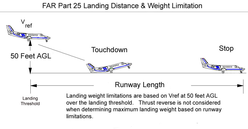
LANDING ( Usually done
at end of flight )
Land and come to a complete stop from 50 Ft AGL and Vref. The total distance required is the sum of the distance from Vref and 50 ft AGL to touchdown, and the distance from touchdown to a complete stop. If operating under FAR part 135 or 121, the actual landing distance must be divided by 0.6 to determine the minimum field length, as the aircraft must be able to land within 60% of the available runway.
Stop without exceeding its brake energy limit. If brake energy may be a limiting factor for landing, a chart will be provided in the AFM allowing the pilot to determine what the brake energy limited weight is.
Climb (Minimum 3.2% gradient) in landing configuration with all engines operating. (Balked landing Climb)
Climb (Minimum 2.1% gradient) with landing gear up, flaps at the approach setting, and one engine inoperative. (Approach Climb)
If these requirements can not be met at the maximum
certificated landing weight, the maximum landing weight is reduced such
that the above requirements can be met. These performance limits are "Operating
Limitations". They define the maximum landing weight for the particular
situation at hand. Again, these are "Operating Limitations", not just advisory
information.