 |
|
|
|
|
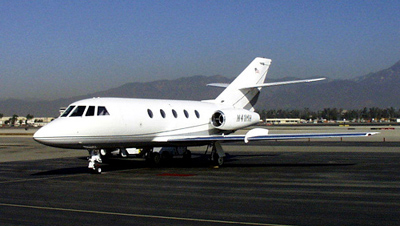
The Jurassic Jet
As you can see, the Falcon 20 is a good looking airplane. The
nice thing is, it flies as good as it looks. The entire Falcon line
are all airplanes that just plane feel good to fly. I have flown
most of the Falcon aircraft, and all of the flight simulators. They
all fly well. The 2000 is my personal favorite.
|
|
|
|
The Falcon 20 is a great airplane. It has a
spacious cabin, and comfortable pilot seats. If you want to set records
for speed and range, look elsewhere. It was limited by engine design.
The CF-700 is a very reliable engine, but is a bit of a gas hog.
The 731 Retrofit and the Falcon 200 do a bit better because of more modern
fuel efficient engines.
|
|
Weights
|
|
|
|
|
|
| Max Ramp
SB 465 |
28,660 lbs |
28,660 lbs |
|
|
| Max Takeoff
SB 465 |
28,660 lbs |
28,660 lbs |
|
|
| Max Landing |
|
|
|
|
| Max Zero Fuel
SB 363 |
22,000 lbs |
22,000 lbs |
22,000 lbs |
22,000 lbs |
Vmo / Mmo
|
|
|
|
|
|
| Sea Level |
|
|
|
|
| @ 23,400 msl |
|
|
|
|
| Mmo |
|
|
|
|
Vfe
|
|
|
|
|
|
|
|
|
|
|
|
|
|
|
|
|
|
|
|
|
|
|
|
|
|
|
|
|
|
|
|
|
|
|
|
Vmc
|
|
|
|
|
| CF-700 -2C or -2D |
30 deg |
100 kts |
98 kts |
| CF-700-2D2 |
30 deg |
102 kts |
100 kts |
| Falcon 20 F Model |
|
|
|
Misc. Speeds
| DV Window |
|
| Landing Lights |
|
| Vlo |
|
| V airbrake |
|
| Vle |
|
| Windshield Wipers |
|
| Total Hydraulic Failure |
|
| Max Altitude
Cruise Takeoff & Landing DLE & Flaps |
10,000 ft 20,000 ft |
| Max Tailwind Component T.O. & Land |
|
| Demonstrated Crosswind |
|
| Pressurization Limits / Norm
Relief |
8.5 Psid |
| Max Slush / Takeoff & Ldg |
|
|
|
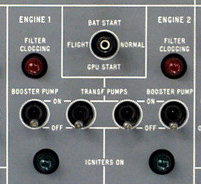
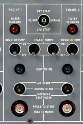
The Falcon 20 has a unique fuel system. The
fuel is stored in the wings, and in two "Feeder Tanks" located in the forward
portion of the tailcone compartment of the airplane. Each wing tank
contains an electric "Transfer" pump. The "Transfer" pump pumps fuel
from it's own wing to the feeder tank on the same side, keeping the feeder
full, or near full until the wing fuel is exhausted. The wing tanks
are connected by an "Interconnect" valve. This valve allows fuel
to be moved from one wing tank to the other. To do this, Open the
"Interconnect" valve, and turn Off the Transfer pump on the side you wish
to transfer FROM. The operating pump sucks
the fuel from the tank who's pump is off, and sends it to the feeder tank
on it's own side. The "Crossfeed" valve connects the feeder tanks.
It allows one feeder to supply fuel to either or both engines. With
the Crossfeed open, and the left boost pump off, the right feeder tank
supplies fuel to both engines.
This may seem strange, but it does allow use of
all of the fuel with any two pumps failed. For example, lets say
that both fuel pumps on the right side have failed. Open the Interconnect
and the Crossfeed valves. The Left fuel pumps are working, but not
the right. The left transfer pump sucks fuel from the right wing
and sends it to the left feeder tank. The left Boost pump provides
fuel to the left engine, and also to the right engine thru the crossfeed
valve. So, all of the wing fuel, and the left feeder fuel can be
delivered to the engines under pressure. The right feeder fuel, if
needed, must be suction fed.
The wings are pressurized to about 3 psi by bleed
air. This will cause most of the wing fuel to transfer to the feeder
tanks in the event of electrical failure.
Starting with a full airplane, the engines receive
fuel from the feeder tanks only. The fuel transfer pumps keep the
feeders full until the wing fuel is gone. Then the feeders begin
to empty. When the feeder tanks are empty, good luck, you are now
a glider.
Refueling is done over wing, or by a single point
refueling system if installed. Without single point refueling, the
feeder tanks are filled from the wings by the "Transfer" pumps.
 |
|
|
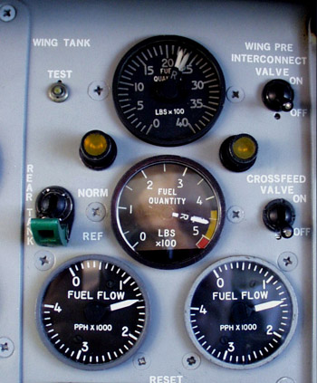
As you can see, you have two double needle fuel gauges,
one for the wing tanks and one for the feeders. you should be on
the ground prior to the wing fuel being depleted. The feeders on
all but the C model only give you about 20 minutes at low altitude.
The large feeders give only another 10 minutes more than the small ones.
Stay ahead of this. A clear day with another airport within 10 or
20 miles is one thing, but that is not always the case. Don't put
yourself in a position with only one acceptable option.
 |
|
( Overhead Panel ) |
Fuel Capacity
| Standard |
|
|
| With SB 278 |
|
|
| D & E |
|
|
| F Model |
|
|
This may seem like lots of fuel, however, the first
hour uses close to 3,200 lbs. The second hour sucks up around 2,500
lbs or so at 440 knots. Long range cruise is still around 2,000 lbs
per hour at 400 knots. This means you can go fast for about two and
a half hours, or long range cruise it and go about 3 hours. In a
no wind situation, this means about 1,100 to 1,200 nautical miles in good
weather with no headwind. Nonstop coast to coast, sure, in Panama
or Costa Rica!!! The 731 Conversion Falcon will do about 1,800 nautical,
and the Falcon 200 maybe a little bit more.
|
|
|
L Hyd Pump |
R Hyd Pump |
| Ailerons | Ailerons |
| Elevator | Elevator |
| Rudder | Rudder |
| Airbrake | Yaw Damper |
| Nose Steering | Aileron Variable Belcrank |
| Landing Gear | Elevator Variable Belcrank |
| Trailing Edge Flaps | Emergency Gear Extension |
| Leading Edge Flaps | Emergency Gear Door Extension |
| Parking & Emergency Brakes |
The Aux hydraulic pump can be used to power System 2 Flight Controls Only. It can power all of the System 1 devices if the aircraft has a reasonable Mod / Service Bulletin status. It does, however, depend on the individual airplane. Pressure from System 2 can be used to perform limited System 1 functions with the 0.58 gallon "Transfer Jack" if it is charged prior to the System 1 pump failure.
System 1 Failure
| Landing Gear |
Gear Doors Remain Open |
| Flaps |
|
| Airbrake |
|
| Brakes |
No Anti Skid |
System 2 Failure
| Landing Gear |
|
| Flaps |
|
| Airbrakes |
|
| Brakes |
|
|
|
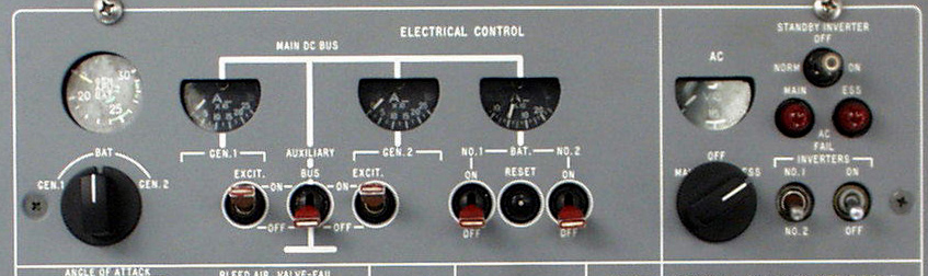
Below, you see a typical Falcon 20 Electrical Control
Panel. It is on the top of the overhead switch panel in the center
of the overhead. There are many inverter systems available on the
Falcon 20, but none are really beyond comprehension. The DC side
is fairly standard.
Don't forget to turn the Aux Bus off when shutting
down the airplane if you plan to use the batteries without a trip to the
shop.
 |
|
|
|
|
Engine bleed air provides air conditioning and pressurization.
It comes from the 8th stage compressor of each engine. It goes thru
a heat exchanger and a cooling turbine in order to reduce the temperature.
Temperature is regulated by a temperature control valve that is electrically
actuated. Both AC and DC power are required to electrically control
the temperature. Manual and automatic temperature control is available.
One problem with the manual system is that there is no valve position indicator,
so a lot of guessing is necessary. The valve takes over a minute
to go from full cold to full hot, or back.
Pressurization is regulated by an electric system
in automatic, and by pneumatically positioning the outflow valve.
Crude but effective. In automatic, it works quite well.
The 8th stage engine bleed air flows through heat
exchangers, then through a cooling turbine and into the cabin. The
cooling turbine drives a compressor that provides ejector air, increasing
the airflow across the heat exchangers. Temperature control is achieved
via a temperature control valve that regulates how much bleed air goes
thru the cooling turbine, and how much bypasses it.
APU air provides air conditioning and electrical
power on the ground only. There is not a whole lot to monitor as
far as the APU goes. It has an rpm gauge, an amp gauge, and that's
it. Everything else is automatic.
|
|
The CF-700 is one of the early fan engines. It is really just a CJ-610 with a free wheeling fan mounted on the back. This raises the thrust from around 3,000 lbs to the 4,100 lb to 4,500 lb range. There is some improvement in specific fuel consumption. If the CJ-610 or it's variant was to power an airplane over 20,000 lbs gross weight, it needed the fan and the new name to do it. Prior to the introduction of the 731 Engine, the CF-700 was the only way to go. It is also found on one model of the Saberliner.
Engine Limitations
|
|
|
|
|
|
|
| Start / 5 Sec |
|
----- |
|
|
- 54 C / Type 1 |
| Takeoff
2D2 |
|
|
740 C |
|
185 C |
| Max Cont
SB 455 GE 77-7 2D2 Engine |
|
|
724 C 724 C |
|
|
Note: The N1 is the engine core, and the N2 is the fan section. This is the only popular biz jet engine where this is the case. Remember, the fan is on the back of the engine.
Engine Thrust
| CF-700 2C |
|
| CF-700 2D |
|
| CF-700 2D2 |
|
| CF-700 2D2 / SB 520 |
|
 |
|
|
| Recomended Minimum N1 | |
| SL to 12,000 ft |
|
| 12,000 ft to 25,000 ft |
|
| Above 25,000 ft |
|
|
|
There are 7 diferent APU options on the Falcon 20.
The switches and gauges are different. See the AFM Suppliment for the particular
airplane you intend to fly for APU Limitations and Operating Procedures.
|
|
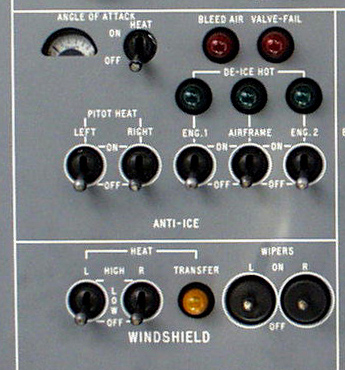
The Windshields are electrically heated, as are the
Pitot Tubes & AOA vanes. The engines and wing are anti iced with
hot bleed air from the engines. The tail is not heated, as not enough
ice will form there to be a problem. The use of anti ice on takeoff
will probably reduce your maximum takeoff weight by between one thousand
and two thousand pounds. With the engine and the wing heated up,
the Falcon 20 performs like a very large, very fat pig. That is the
nicest way I can think of to say it, and I like the airplane!
It takes several minutes to get the wing up to temperature,
and a bit less time to heat up the engine nacelles. Think ahead and
heat 'em up early if you are going to need them.
The red lights tell you if the valves are operating
properly, and the green ones illuminate when the temperatures reach a safe
level for operating in icing conditions. They take a while to come
on after the system has been activated, and stay on for a short time after
the anti ice is turned off. This is normal
If you must use engine anti ice or both engine and
wing heat, you may have to make the approach with the airbrake extended
in order to have enough bleed air to do the job. If so, remember:
1. If the Airbrake is not retracted by 500 ft AGL,
Land with it Extended. Add 5 or 10 knots to your approach speed,
as your stall speed will increase.
2. If you are unable to turn off the wing heat
immediately after Landing, shut both
engines down on the runway or ruin the leading edges. They cost big
bucks.
 |
|
( Overhead ) |
The amber Transfer light alerts you to the fact that
one of the windshield heat controllers has failed, and the other is regulating
all the heated windows. It works fine like this, and from a pilot
standpoint is a maintenance write up and a possible MEL item.
|
|
|
|
|
|
|
|
|
|
|
|
|
|
|
|
|
|
|
|
Remember: It takes time to heat up. Extension
of the airbrake may be necessary in order to comply with this chart.
ATC may ask you to slow down, give your best rate of descent, and God knows
what else. Your airplane can only do what it can do. Comply
with reasonable requests when you can, but don't hesitate to say "Unable"
when necessary. You are the Captain ATC tries to do a good job, and
usually does, however, they are not usually qualified to fly your aircraft,
nor will they die in the crash.
|
|
Here are some basic flight profiles that I have used over the years. They are not the only way to fly the airplane, but have worked for me since I started giving training and checkrides in the Lear a little over 20 years ago. In the event of a difference between this and the Aircraft Flight Manual, the flight manual is the document to follow.
Steep Turns
1. Enter at 250 KTS indicated AIRSPEED.
2. Bank aircraft 45 deg. As you pass 30 deg of bank, pitch
up 2 deg. Add power to maintain AIRSPEED.
3. Lead roll out by 15 deg. Passing 30 deg bank, pitch
down 2 deg to maintain altitude.
4. Maintain 250 KTS and assigned heading.
Stall - Cruise Configuration
1. Compute Vref & set AIRSPEED bugs.
2. Maintain assigned altitude and set power to Idle.
3. Trim for level flight until reaching trim stop
for Zero Flaps
4. At first indication of a stall, throttles
to " MAX POWER "
5. Call " MAX POWER Flaps 15 deg.
6 Reduce pitch ONLY to the extent necessary
to eliminate symptoms of the stall.
7. Reestablish assigned altitude.
8. At Vref + 30 KTS, call " Flaps Up, After Takeoff
Checklist. "
9. Maintain AIRSPEED and altitude as directed.
Stall - Takeoff Configuration
1. Compute Vref, set AIRSPEED bugs & select flaps 15 deg.
2. Maintain assigned altitude and set power to 70% N1.
3. Trim for level flight until passing 150 KTS.
4. Maintain altitude with necessary back pressure.
5. At first indication of stall, advance throttles & call
" MAX POWER ".
6. Level wings & reduce pitch ONLY to enough to eliminate
symptoms of the stall.
7. Reestablish assigned altitude.
8. At Vref + 30 KTS, call " Flaps Up, After Takeoff Checklist.
"
9. Maintain AIRSPEED and altitude as directed.
Stall - Landing Configuration
1. Slow to flap speed, set 80% N1 & Set bug to
Vref.
2. Maintain assigned heading & altitude.
3. Below 200 KTS, " Flaps 15 deg".
4. Below 190 KTS, " Flaps 25 deg".
5. Gear Down Landing Check.
6. Below 180 KTS, " Full flaps. " trim to Vref. Establish
a 400-700 feet/min sink rate at Vref.
7. Level off at designated altitude W I T H
O U T increase in power
8. Maintain altitude until first indication
of a stall.
9. Apply MAX power lower nose only as much as required
to eliminate the stall warning.
At Vref minus 10 KTS M I
N I M U M speed, call for " Flaps 25 deg",
At Vref call for " Flaps 15 deg",
10. When VSI & Altimeter indicate positive rate of climb
call " Positive rate, Gear Up ".
11. Establish 7.5 deg nose up attitude.
12. At Vref + 30 KTS, Call " Flaps Up, After Takeoff Checklist
".
13. Return to entry heading and altitude or as directed.
ILS Approach - Two Engines
1. Intercept LOC at 140-160 KTS and Flaps 20 deg.
2. One dot prior to intercepting Glide Slope, call " Gear Down
Landing Check ".
3. When ON the glide path, call " Full Flaps ".
4. Establish Vref to Vref + 5 KTS & track LOC & GS until
Minimums.
ILS Approach - One Engine
1. Intercept LOC at 140-160 KTS and Flaps 8 deg.
2. One dot prior to intercepting Glide Slope, call " Gear
Down Landing Check ".
3. When ON the glide path, call "Flaps 25 deg".
4. Establish Vref + 15 KTS & track LOC & GS
5. At 100 Ft AGL, Full flaps, power idle & land.
F Model requires power down to flare
altitude.
Non Precision Approach - One or Two Engines
1. Intercept Final Approach Course at 140 KTS and
Flaps 25 deg.
2. Crossing Final Approach Fix, call " Gear Down
Landing Check ".
3. Descend to and maintain MDA until Field in Sight
or MAP is initiated. ( As Appropriate ).
4. If Landing is to be made, call " Full Flaps "
when intercepting a glide path appropriate for a
normal landing. For one
engine INOP, Vref + 15 KTS until 100 feet AGL, then " Full
Flaps" so as to descend thru 50
ft AGL at Vref as in a normal landing.
No Flap Approach
See Chart in AFM for speed adjustments for specific situation.
Go Around or Missed Approach
1. "Max Power", Rotate to 10 deg, " Flaps 15 deg".
2. Positive Rate of Climb, " Gear Up ", Vref + 30, " Flaps up,
After Takeoff Checklist ".
3. Climb at 200 KTS.
4. Engine Failure or Fire Checklist if Appropriate.
Takeoff
1. Set V2 on Capt. Airspeed & V1 on Co-Pilots Airspeed.
2. At V 1, BOTH hands on Yoke.
3. Vr, Rotate to 15 deg ( 2 eng ) 12 deg ( 1 eng ).
4. Climb at 15 deg pitch, ( 2 eng ) or V 2 ( 1 eng ).
5. At 400 ft & V2+30 KTS, "Flaps Up After T.O. Check ".
6. Engine Failure or Fire Checklist if Appropriate.
7. Climb 200 KTS to 3000 AGL then 250 Kts.
Rejected Takeoff
1. Proceed as in normal takeoff until malfunction dictates that
the takeoff be rejected.
2. Capt. calls "Abort" (Co-Pilot may call Abort if Capt elects
to delegate that authority).
3. Thrust levers to idle
4. Airbrake extend.
5. Wheel brakes as necessary.
6. Thrust Reverse OR Drag chute deploy. (Never Both!)
7. If another takeoff is contemplated consider brake energy &
appropriate turnaround time.
Emergency Descent
1. Oxygen masks on within 5 sec of cabin pressure
loss.
2. Check passenger oxygen masks deployed.
3. Select Oxygen mask microphone.
4. Ignition ON.
5. Thrust levers to idle.
6. Auto Pilot OFF
7. Airbrake extend
8. Initiate 45 deg bank if desired.
9. Vmo/Mmo minus 10 kts to 14,000 or MEA as
required.
10. Clean up & proceed to nearest suitable airport if appropriate.
Condition of aircraft or
reduced range due to low altitude
may make flight to original destination unwise.
BackToAirplane Driver Home Page