
|
|
|
|
|
S t u d y G u i d e
|
|
The following is an overview of the basic systems on
the Gulfstream II. It does not address the winglets that may be installed.
They give the airplane about 20 minutes more endurance and cost about half
a million dollars. Other than including some limitations, I did not
discuss the tip tank airplanes because they are just too ugly and were made
obsolete by the G II-B; a G II with a G III wing.
It is not intended to provide enough information for you
to build the airplane. It is intended to provide general information for
familiarization and review. This guide addresses only the G II.
The G II-B has it's own study guide on this web site. For the
latest and most accurate information, refer to the current
AFM. Many flight manuals on older airplanes, if subjected
to inspection, will be found to be out of date. Guess who gets the shaft
if there is a problem, and you were operating with out of date information.
Look in the nearest mirror and see!
|
|
Gulfstream II
|
|
|
|
|
|
|
|
|
|
|
|
|
|
|
|
|
|
|
|
|
|
|
|
|
|
|
|
|
|
|
|
Weights
|
|
|
ASC 81 |
|
|
|
| Max Ramp |
|
|
|
|
|
| Max Takeoff |
|
|
|
|
|
| Max Landing |
|
|
|
|
|
| Max Zero Fuel |
|
|
|
|
|
The above weights are maximum certificated limits. The actual maximum weights for a particular flight may vary due to the performance limitations. If the aircraft can not meet the required "Takeoff Field Length" and "Climb" limitations, (engine out climb performance), the maximum takeoff and/or landing weights are reduced such that the requirements are met. See the performance charts in the AFM for details.
Speeds
| Vmo / Mmo With ASC 200 Vsb / Msb With ASC 200 |
300 kts SL / 338 kts @ 28,100 ft 338 kts / 0.85 Mach 300 kts / 0.85 Mach |
| Va With ASC 200 Vb With ASC 200 |
160 kts 275 kts / 0.75 Mach 257 kts / 0.75 Mach |
| Vfe 10 Deg 20 Deg 39 Deg |
220 kts 170 kts |
| Vlo Vle Emergency Ext. |
250 kts / 0.70 Mach 175 kts |
| Vmcg Vmca |
102 kts |
| Mach Trim Inop |
|
Holding Speeds
|
|
|
|
|
|
Note: More exact holding speeds may be derived from the aircraft's performance documentation, however, there will not be a whole lot of difference unless your weight is greater than 46,000 lbs. The 200 knot figure is a legal holding speed at any altitude. Above 46,000 lbs. add about 2 knots per thousand pounds additional weight. If you need to hold at a speed higher than 200 kts, and don't have the AIM handy, just request your desired holding speed with ATC. Any speed ATC approves is legal, just ask. Holding fuel flow at 46,000 lbs varies from about 3,800 lbs / hour at sea level to 2,900 lbs / hour at 15,000 ft. At heavier weight, add about 50 lbs / hour per 1,000 lbs above 46,000 lbs.
Recommended Minimum Maneuvering Speeds
|
|
|
|
|
|
|
|
|
|
|
|
|
|
|
These speeds should keep you out of trouble if you keep the bank angle under 30 degrees. Cross check the Angle of Attack Indicator. Keep it in the green!
Altitudes & Misc.
| Max Alt T.O. & LDG With Supplement G-II-79-19 |
13,360 ft |
| Max Enroute Altitude / ASC 299 Standard Max Altitude Flap & Gear |
43,000 ft 20,000 ft |
| Min Temp T.O. & LDG Max Slush Max Water |
0.75 inch 0.50 inch |
| Max Temperature Abv 10,000 ft |
ISA +30 C |
| Min Temp SL - 3,500 |
|
| 3,500 - 5000 Linear |
|
| 5,000 - 10,000 |
|
| 10,000 - 35,000 Linear |
|
| Above 35,000 |
|
| Max Demonstrated X-Wind |
|
| Max Runway Slope |
|
| Max Tailwind Component T.O. & LDG |
|
| Load Factor Limit Flaps Up Flaps Extended |
2.00 G |
Turn Clearance Limits
|
|
|
|
|
|
|
|
|
|
|
|
|
|
|
Spey Mk 511-8 Engine Limitations
|
|
|
|
|
|
|
|
|
|
|
|
|
|
|
|
|
|
|
|
|
|
|
|
|
|
|
|
|
|
|
|
|
|
|
|
|
|
|
|
|
|
|
|
|
|
|
|
|
|
|
|
|
|
|
|
|
|
|
|
|
|
|
|
|
|
|
|
|
|
|
Engine Oil System Limitations
| Min / @ Max Continuous |
|
| Min / Idle |
|
| Min To Complete Flight @ Max Cont. |
|
| Min To Complete Flight @ 92% N2 |
|
| Min To Complete Flight @ 84% N2 |
|
| Min To Complete Flight @ 52% N2 |
|
| Max Oil Temp |
|
| Max Transient Oil Temp / 15 Min |
|
| Min Oil Temp for Start Min Oil Temp Above Idle |
-30 C |
|
|
The flight controls on the G2 are cable driven with hydraulic boost. They are powered by both the "Combined" and "Flight" hydraulic systems. Each of the systems provides 1500 psi to the flight control servo actuators. When the landing gear or flaps are extended, the combined system pressure increases to 3,000 psi. If one system fails, the remaining system pressure increases to 3000 psi. Failure of one hydraulic system therefore, does not result in a loss of control effectiveness.
Ailerons
The hydraulically boosted ailerons provide roll control. Either or both hydraulic systems will power the ailerons. They are assisted by the flight spoilers. A bungee connects the spoiler mixer and aileron on each side so that the ailerons and spoilers can be moved regardless of the status of the the other. Roll trim is provided by a trim tab located on the left aileron. The aileron trim tab is set with a manual trim wheel in the cockpit. No electric stuff here!
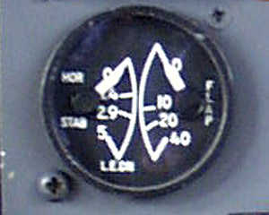
Elevator
The Gulfstream II is equipped with a moveable stabilizer, elevator, and elevator trim tab system. The elevator is hydraulically boosted by both hydraulic systems.. Elevator trim adjustments are made with the manual trim wheel in the cockpit, or electrically from the control yoke. The stabilizer is automatically adjusted when the flap setting is changed in order to compensate for changes in trim caused by flap extension and retraction. The stabilizer is moved via a gearbox in the tail. The flap gearbox is connected to the gearbox in the tail. The stabilizer position is indicated by a gauge within the flap position indicator. If the stabilizer does not position itself properly with each change in flap setting, return to the previous setting and go to the checklist. The aircraft may be landed safely with the stabilizer out of trim, however, much higher than normal control forces may be required, as the trim will not be as effective.
Rudder
The rudder, like the rest of the flight controls
on the Gulfstream, is hydraulic. Rudder trim is provided by redefining
the neutral position with the rudder trim wheel in the cockpit. The
maximum rudder travel is 22 deg each side of center. The rudder may
be trimmed 10 units, or 7.5 deg either side of center. The yaw damper
is a full time system, powered by the "Flight" hydraulic system. It
has 3 deg of authority each side of wherever the trim and pilot input would
place the rudder. If the "Flight" hydraulic system fails, the yaw damper
is inop.
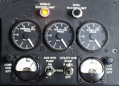
The rudder on the G2B is equipped with a single and a
dual load limiter system. These systems limit the forces applied to
the rudder in order to avoid structural failure of the tail at high speeds.
This single rudder load limiter system limits hydraulic pressure to a maximum
of 2650 pounds to the rudder actuator to avoid excessive loads on the aircraft
at high speeds. The dual load limiter system further limits the pressure
to 2250 pounds. If only one of these two systems is operable, and you
have an MEL for the aircraft, you can fly. The rudder load limiter
systems have two indicator lights, an amber one for the single rudder load
limiter system, and a green one for the dual rudder load limiter. Before
start, the amber light should be on. Only after both engines are running,
the amber light will go out, indicating that the single rudder load
limiter system is working. When the combined and flight hydraulic
systems are operating, the dual rudder load limiter may be checked.
This is done by slowly depressing one rudder pedal to the floor, and looking
for a green light to illuminate at full rudder deflection. Now press
the other rudder pedal to the floor, and the green light should illuminate
again, indicating that the rudder has reached it's mechanical stop, and the
dual rudder load limiter is in fact limiting the pressure. If you get
the green light in one direction but not the other, check the rudder trim
and verify that it is centered. If not, center it and repeat the test.
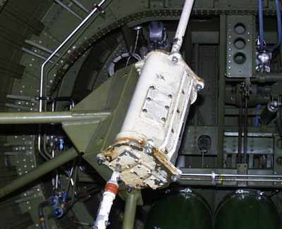
Flaps
The flap system is hydraulic. Flaps may be extended
to 10 deg, 20 deg, and 39 deg with the normal system. The alternate
flap control system can be used to extend or retract the flaps to any setting
between 0 deg and 39 deg. The flaps may be operated by "Combined",
"Utility", or "Aux" hydraulic systems. When the flaps are moved, the
horizontal stabilizer is repositioned via a gearbox depicted below.
|
|
|
|
|
|
Because it changes the angle of incidence of the
horizontal stab, it minimizes trim changes during flap extension and retraction.
Flap asymmetry protection is provided via electrical signals from the outboard
flap jackscrews. The flaps system will stop if there is 1/4 inch or
more difference in the linear travel of the flap actuators. A torque
limiter prevents damage to the system in the event of a jammed mechanism
or an attempted extension at excessive airspeed. A flap assymetrey
will not reset until it is fixed. If flap movement is arrested, it
is either loss of hydraulics, flap assymetry, or torsque limiting.
If it was torque limiting, slow the airplane down to within the limiting
speed for the flap setting you tried to get. Retract the flaps to the
previous setting, then re-extend at the proper airspeed. If this restores
flap operation, it was in fact the torque limiting system just doing it's
job. The airplane flies just fine if you stay clean until around 200
knots. Extending the flaps at less than the limiting speeds will minimize
the unwanted pitch activity during flap extension.
In the event of unwanted flap movement, the flaps may
be stopped, and the flap selector disabled by a switch on the copilot's lower
arm ledge. With this switch activated, the flaps are moved by the emergency
flap control. Any setting between zero and full may be selected.
You still have flap asymmetry protection in the emergency mode.
Max Flap Extension Speeds
|
|
|
|
|
|
|
|
|
Flight Spoilers
All G2's and G3's have six spoiler panels, three on each wing. All G II's, the first eleven G II-B's and G III's # 386, 389, and # 384 and earlier have what is referred to as the "Four Panel System". This addresses the fact that on the "4 panel" airplanes, the inner two panels only extend when ground spoilers are deployed. The outer 4 panels extend when speedbrakes are selected, and all extend in the ground spoiler mode . The speedbrake system uses the outer two panels on each wing. They may be extended to 43 deg with the speedbrake handle. In a turn, the spoilers on the lower wing will extend to 55 degrees in conjunction with full aileron deflection. All of the "4 panel" airplanes have a "Ground Spoiler Deact Handle" on the center pedistal in the cockpit. The Flight Spoilers / Speedbrakes are powered by both the "Combined" and "Flight" hydraulic systems. Speedbrakes may be extended with up to 20 deg of flaps. Spoiler / Speedbrakes may not be deployed in flight with the flaps more than 20 deg, or with the Landing Gear extended. The Flight Spoilers also assist in roll control, as they operate selectively with the ailerons. A bunge allows aileron movement in the event the spoiler is stuck.
Ground Spoilers
The "Ground Spoiler" system extends the inboard spoilers to 55 degrees. At the same time, it extends the speedbrakes to 55 degrees as well. This is done only when both nutcracker switches are in the ground mode, both thrust levers are at ground idle (hard stops), and the ground spoiler switch is armed. The ground spoilers may not be armed without a successful nutcracker test after gear extension.
Four Panel Speedbrake Systems
|
|
|
| Max Aileron, 0 Speedbrake |
|
| 0 Aileron, Max Speedbrake |
|
| Max Aileron, Max Speedbrake |
Up wing 43 deg |
| Auto Ground Spoilers |
|
Nosewheel Steering
Ground steering is provided by a hydraulically actuated steerable nosewheel. The nosewheel may be steered 82 degrees each side of center. The nose steering is powered by the "Combined" or the "Utility" hydraulic systems. In the event those systems are inop, differential braking may be used for directional control on the ground. In order to use differential braking to steer, you must turn the nosewheel steering system off. This is done with a red guarded switch located just forward of the tiller. The nose steering system is disabled unless the nut crackers are in the ground position. Loss of Main DC Bus power has the same result as turning the nosewheel steering system off.
Brakes
The normal braking system provides braking to all of the main gear wheels. The main wheel rotation is arrested during gear retraction. The combined hydraulic system provides 250 pounds of hydraulic pressure to the brakes during the gear retraction cycle. An anti-skid system provides skid protection during braking with the normal system. This includes protection if the brakes are applied prior to touchdown. The anti-skid system requires Main DC Bus power. The parking / emergency brake is powered by an accumulator. Use of the emergency brake system usually blows the tires, as it is almost impossible to modulate, and locks the main wheels.
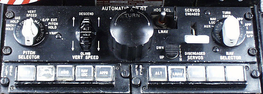
Autopilot
Gulfstream II SN # 1 thru 238 (except 220) were
delivered with the Sperry SP-50G autopilot. The SPZ-800 autopilot
was installed on # 239 and later. In this guide, we will address the
SP-50G. The SPZ 800 will be discussed in the G III study guide. The
SP 50-G is the older of the two systems, and was a commonly installed in
the Boeing 727-100, and earlier 727-200 airplanes. It is a great system
even today, It can even be certified for MNPS and RVSM if the appropriate
mods are done the the aircraft.. It provided all of the basic autopilot
functions such as wing leveling, heading hold, NAV and will intercept and
fly an ILS approach if properly set up by the crew. Altitude preselect
is an option, but should be found on most G II-B's. Do not engage "Manual
Glideslope" unless you are within a quarter of a dot of on glidepath.
Although it is not a limitation, if you are more than half a dot away
from dead center on the glide path it will capture, but you and your
passengers may not like that portion of the ride. Avoid the same mistake
on your next job! Manual Glideslope is normally used to capture the
glideslope from above. If you are intercepting from below, AutoGS is
a much better idea.
Unlike many of the crude autopilots of it's day, the SP-50
works well in the IAS and Mach speed modes. It does, however, lack
a half bank mode. It is a bit on the aggressive side when capturing
a new course at a waypoint change. For passenger comfort, switching
to heading mode until established on the new course is better. The SP-50G
is not integrated with the flight director system.
|
|
|
SP-50G Autopilot Limitations
| Do not operate the SP-50G Autopilot: |
| Above Vmo/Mmo |
| Below 1.2 Vs |
| Below 38,000 lbs and aft of 43% MAC CG |
| With Yaw Damper Inop |
| Above 35,000 ft with an engine inop. |
| With Autotrim inop |
| During coupled approaches with an engine inop |
| During takeoff or landing |
| Do not SELECT Manual Glideslope below 1,000 ft AGL |
Although it is not a limitation,
it is highly recommended that you not select Manual Glideslope if you are
more than half a dot away from dead center on the glide path. It will
capture, but you and your passengers may not like that portion of the ride.
Manual Glideslope is normally used to capture the glideslope from above.
If you are intercepting from below, Auto is a much better idea.
|
|
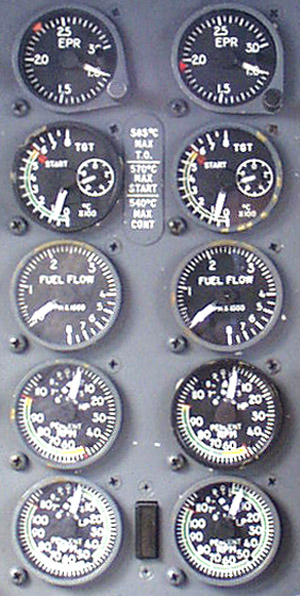
All of the Gulfstream II and III aircraft are powered by two Spey Mk 511-8 engines. These engines are rated at 11,400 pounds of thrust each. The Spey Mk 511-8 is a twin spool axial flow Jet Engine. The LP compressor, (N1 or Fan) is a 5 stage compressor. Some of the air from this LP compressor is routed around the engine core, and provides thrust. The rest of the LP air is ingested into the HP or N2 compressor. The N2 section has 12 compressor stages. Behind the compressor sections is the combustion chamber, then the HP turbine, and finally the LP turbine. The HP and LP turbines drive their respective compressor sections.
Percent vs RPM
|
|
|
|
|
|
Accessories mounted on the engine include oil pumps,
high pressure fuel pump, a hydraulic pump as well as alternator and generator
for each engine. These are driven by the HP or N2
section. The engine oil is cooled by fuel via a fuel / oil heat exchanger.
It heats the fuel and cools the oil. Oil pressure indications are provided
by an AC powered gauge and a DC powered low pressure light (Idiot Light)
for each engine. There is an engine oil replenishing system installed
on Gulfstream Jets.
Engine oil may be serviced only on the ground.
Variable inlet guide vanes, and farther back, a surge
bleed valve on the 7th compressor stage are installed to stabilize the engine
idle, prevent compressor stalls, and optimize the engine acceleration characteristics.
A malfunction of the surge bleed system will result in unstable idle, poor
acceleration, and compressor stall in many instances.
|
|
|
|
|
|
TVI
Vibration is monitored in the engine with the TVI or
Turbine Vibration Indicator system. This system allows the crew to
monitor the engine vibration. This can alert the crew of impending malfunction
or failure of the rotating engine components. Some vibration is normal,
however a change in vibration level may indicate impending doom for the engine.
See the chart below.
|
|
|
| Increase of 1.0 or more during steady state operation | Slowly close thrust lever & observe vibration during deceleration. Make an note of the maximum value. If less than 3.0 (3.5 between 67% and 74% N2), restore power and monitor engine instruments. |
| A sudden increase of 3.0 (3.5 between 67% and 74% N2) | Perform engine shutdown if situation permits. Monitor engine warning systems. |
| During start, Increase of 3.0 or more. | Abort the start. |
| During shutdown, Increase of 3.0 or more. | Record incident and have engine inspected. |
Fuel Heat
An automatic Fuel Heating system is installed on these engines. This is to prevent any ice formation in the engine fuel system. The fuel is heated by P3 bleed air, and monitored by fuel temperature gauges in the cockpit. These gauges are powered by the essential DC bus. Some fuel heating does result from the fact that the hydraulic systems have heat exchangers in the hopper tanks, however the intent of these is to cool the hydraulic fluid. The fact that the fuel is heated a small amount is not important.
Top Temp Control
A temperature control and limiting system is installed
on the Spey 511 Mk-8 engine. This system, if on, will prevent a TGT
overtemp. The temp control amplifier is powered by the 115 Volt AC instrument
Inverter Bus. The Top Temperature Control System is to be ON except
in the event the system fails.
|
G II & G II-B |
Note: All APU's installed in G II's, G II-B's and G III's with the DC Electrical System are limited to ground operation only. All G III's have the GTCP 36-100 APU, but only the AC models, G III # 357, # 402 & Sub except # 875 are certified to operate in flight. Do not think that just because you may have the GTCP 36-100 APU that you can operate it in flight. You can't , except for the late G III's listed above.
The great thing about the APU on the Gulfstream is that it will allow
you to start the engines and go someplace, instead of just sitting on the
ramp. The APU on the G2 is for ground operation only. It can
provide air for engine start, or air conditioning, as well as AC electrical
power. Some of this AC may be converted to DC with the Emergency TR.
The DC can then power the inverters, providing constant frequency AC.
So, in a round about way, the APU can power the entire airplane on the ground.
Even with the 200 Amp TR, you have plenty of DC for the task, unless you
get stupid with an excessive number of boost pumps and landing lights.
If your TR load is excessive, disconect one of the batteries for a minute
or so. Let the other battery charge, then place the remaining battery
back on line. For normal operations, you do not need the optional 300
Amp TR. It is mostly a G III thing.
|
|
|
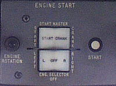
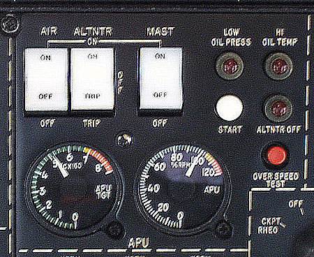
To start the APU, turn on the APU Master Switch. Wait for the
Low Oil Pressure light to illuminate, indicating that the APU door is open.
Press and release the start button, and wait. When the APU RPM is stable
at 100%, turn on the Alternator. Check that both AC busses are powered,
then select the Emergency TR Main & ESS. The ESS only position
is primarily for use in flight for split buss operation. Caution:
Do not open the APU air valve unless the Main DC Buss is powered.
Doing so will result in a very quick overheat of the bootstrap unit, as the
control for the ground cooling fan is on the Main DC Bus. If the Main
DC Bus is not powered, the ground cooling fan will not come on.
Check that the DC Volt Meter reads 26 Volts. The
DC Emergency Feeder light should be illuminated, indicating that the emergency
TR is powering the Main and Essential DC Busses.
The APU Air must be turned on if you wish to do anything
really festive, like start the engines or use the heating / air conditioning
system. Do not run the engines much above idle with the APU Air Valve
Open, as this is not good for the APU.
To shut down the APU, turn off the Air and Alternator,
let the temperature stabilize, then press and release the "Overspeed" test
switch.
Note: Performing a "Nut Cracker" test with the APU
running will shut it down, as the APU will think that the airplane has just
become airborne. I learned this from experience. The bright side
is that I was the only occupant of the aircraft at the time and therefore
did not have to explain my mistake. The APU is a ground only item on
the G-II aircraft. This remains true even if the dash 100 APU is installed.
The dash 100 is certificated for operation in flight on the later G III's,
but not on any of the G II's.
|
|
Engines / APU
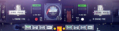
The engines and have continuous wire fire detection
loops in the engine compartments. When heated to their alarm value,
they will cause the engine fire warning system to activate. The respective
left or right ENGINE FIRE lights will illuminate. On # 173 & Sub
and aircraft with ASC 152, fire bell will sound. Press the "Fire
Bell Mute" button to cancel the bell. The fire may be extinguished by
pulling the respective fire handle, and discharging one or both of the engine
fire bottles. Their are two engine fire bottles, each containing 4.5
pounds of Bromotrifluromethane and about 600 psi of nitrogen to disburse
it. Either or both bottles may be discharged into the selected engine.
|
|
|
The APU fire warning is provided by a thermal switch. The APU fire bottle is like the engine fire bottles, only smaller. It contains 2.5 pounds of the extinguishing agent, and the 600 psi nitrogen to distribute it. The APU fire bottle may be fired by lifting the guard and moving the switch. Any fire bottle that is discharged must be removed from the airplane, serviced, and reinstalled. The engine and APU fire detection systems are not part of the Master Warning System.
Note: If you get a fire warning, and perform the appropriate procedure, test the fire detection system after you believe that the fire has been extinguished. If the system won't test, the fire detection loop may have been damaged. In this case, you don't really know if the fire was actually extinguished.
Electrical
Overheat warning is provided for the generators, alternators, TR's, radio rack, and inverters. Some of the warning lights serve two items, such as a TR and an Inverter. These require some diagnosis. Refer to the checklist. The E and B inverters and the B inverter's TR have an auto shutoff feature, as they are located in the radio rack inside the airplane. When the B Inverter shuts down due to an overtemp, it also pops the breaker for the bus it was powering. If one bus caused both it's own inverter and the B Inverter to overheat, the problem is most likely on the bus.
Hydraulic
Overheat warning is provided for the Flight and Combined, systems, and the Aux hydraulic pump. These systems do not incorporate any automatic features to deal with the problem. Consult the checklist for the appropriate procedure.
Pneumatic
The wings, tail compartment, bleed air manifolds, aft
compartment, and bootstrap unit are equipped with overheat warnings.
On the ground, the bootstrap unit will shutdown automatically in the event
it overheats. In flight, the bootstrap unit will only give you a warning,
and must be shut down by the crew. Selecting either Emergency Pressurization
or Ram Air will shut down the bootstrap unit. Emergency pressurization
air is available from the LP compressor on the right engine. The remainder
of the warnings must be handled by the crew.
|
|
The G II Fuel System is simple. Fuel is
stored in the wings. Each wing tank has a "hopper" tank that is kept
full with ejector pumps and gravity. Four DC electric fuel pumps provide
fuel pressure to the engine driven fuel pumps. Warning lights will
illuminate when the hopper tank has 675 pounds of fuel or less. This
amounts to between 20 and 25 minutes at 200 knots IAS at 5000 MSL, or about
50 miles to dry tanks..
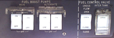
Two of the fuel pumps are designated as "Main", and two
as "Alternate". They are in fact identical. They are located
in the main wheel wells. Normally, all four pumps are on. If
one pump on a given side is turned off, the other pump can supply ample pressure.
In the event that the operating pump fails, and the failed pump's switch
is in the on position, the other pump on that side will come on. The
main fuel pumps are powered by the ESS DC bus. The alternate fuel pumps
get there power from the MAIN DC bus.
You may supply fuel to either or both engines from either
tank by opening the crossfeed valve and switching the fuel pumps off on the
side from which you do not wish to feed. An intertank valve is also
installed, allowing fuel to gravity flow between the tanks.
|
|
|
|
|
|
|
|
|
|
|
|
|
|
|
The airplane burns about 5,000 lbs the first hour, 3,500
lbs the second hour, 3,200 lbs the third hour, then 3,000 lbs per hour thereafter.
Low altitude holding requires 4,000 lbs / hour fuel flow. This gives
you about 6 hours range with 45 minutes worth of holding fuel.
This will take you more than 2,400 nautical miles at normal cruise.
Use of long range cruise will result in additional range. These
are the "No Brainer" figures. With a little time in the airplane and
a few minutes in the book, you should be able to do better.
|
|
The Gulfstream II hydraulic system uses skydol. It has two engine driven pumps, an electric aux pump, and a utility pump that is driven by the "Flight System". This "Utility Pump" is a hydraulic motor, (driven by the flight system) connected to a hydraulic pump that can pressurize the "Combined System" except the flight controls in the event that the combined system pump, or the left engine were to fail. There is no fluid transfer between the flight and combined systems. If the failure of the combined system includes loss of the fluid, the utility pump will not have any effect, as there is nothing for it to pump! The combined and flight hydraulic systems have heat exchangers located in their respective fuel hopper tanks in order to cool the hydraulic fluid. These have nothing to do with the "Fuel Heat" system which is located in each engine's nacelle.
Combined System
The "Combined System" is powered by a hydraulic pump on
the left engine, or in the case of Combined System pump, or engine
failure, the Utility Pump. The utility pump is driven by the Flight System.
The electric "Aux Pump" can power 5 items only. See the chart below.
Flight System
The "Flight" System" is powered by an engine driven hydraulic
pump located on the right engine. It's normal operating pressure
is 1500 PSI. It will operate at 3000 PSI if the combined system pressure
drops below 800 psi. This is to increase the pressure to the flight
controls, and to enable the flight system to power the Utility Pump.
Utility Pump
The Utility pump is a hydraulic pump that pressurizes the
Combined System when it's own pump is not putting out sufficient pressure
for whatever reason. Operation of the utility pump requires at least
2,200 psi flight system pressure. The Utility pump can drive all
of the combined system items except the ailerons, elevator, rudder and flight
spoilers. In the event it is necessary to use the utility pump, those
items are operated by the flight system. If the flight system does
not work, the utility pump won't work either, as the utility pump is driven
by the flight system in the first place!
Aux System
As you can see from the table below, the aux system, in
normal operations, is used on the ground. It allows you to extend and
retract the landing gear doors during the preflight, closes the cabin door,
and provides pressure so you can set the parking brake. It also operates
the Flaps and Brakes on the ground or in flight.
|
|
|
|
|
|
|
| Ailerons | Ailerons | |
| Elevator | Elevator | |
| Rudder | Rudder / Yaw Damper | |
| Flight Spoiler / Speedbrake | Flight Spoiler / Speedbrake | |
|
|
Right Thrust Reverser | |
|
|
Utility System Motor | |
| Ground Spoilers | <<<--- | *Right Thrust Reverser |
| Nose Steering | <<<--- | Flight Sys Reservoir Press. |
| Thrust Reverser(s) | <<<--- | |
| Stall Barrier | <<<--- | |
| Windshield Wipers | <<<--- | |
| Combined Sys Reservoir Press. | <<<--- | |
| <-Aux Pump | ||
| Landing Gear | <<Note: Gear on ground only! | |
| Pedal Brakes | <<<--- | |
| Flaps | <<<--- | |
| Parking Brake | <<<--- | |
| Cabin Door (Close only) | <<<--- |
* Aircraft 123 thru 163, 166 thru 190, 193 thru 198, and those with ASC 138. All others have thrust reversers powered by the combined or utility hydraulic systems.
Note: Use of the Aux Pump to operate the Landing Gear
on the ground applies to the landing gear doors only. The gear doors
are opened on the ground for preflight, and to keep condensation from accumulating
in the main gear doors. If you leave the airplane in an environment
where the temperature goes below freezing, any water that may be in the main
gear doors can freeze, and may interfere with landing gear operation if it
remains during gear retraction, or cause damage on the ground if a chunk
of ice falls out and hits something.
|
|
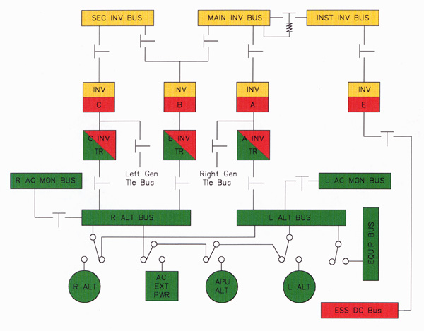
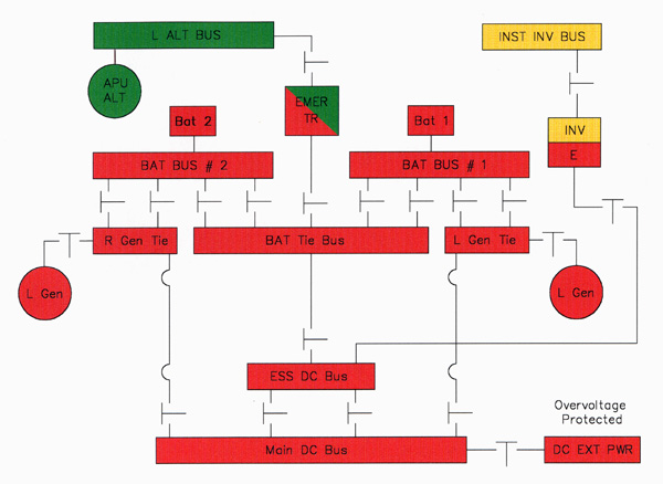
The electrical system on the Gulfstream II may look complicated at first glance, but it is not. It consists of 2 batteries, two 300 amp DC generators, and two variable frequency (wild AC) 115 Volt 20 KVA alternators plus an APU alternator of the same capacity. Not counting the APU alternator, because it can't be used in flight, the Gulfstream II and II-B have 2 DC generators and 2 Alternators. Also they have 4 inverters. Three of these inverters make constant frequency AC from variable frequency AC by using the variable frequency ac to power the A, B, and C Transformer / Rectifiers to make DC from AC. This DC is now used to power the A, B, and C inverters that provide the constant frequency AC power. The "E" Inverter produces constant frequency AC for emergency use. It is powered by the essential DC Bus. The bottom line is, as long as you have at least one of the four electrical generating devices operational, you will have at least the minimum electrical power needed to fly the airplane. In the Gulfsteam, one out of four ain't bad!
Overview
In general, the DC system powers most of the electrical
components on the airplane. The alternators provide power to heat the
windshields, power some interior lighting, and to power the TR's that
produce the DC that powers the inverters. It may sound complicated,
but a peek at the electrical schematic will make it a bit less confusing.
The inverters supply the 400 hz AC that is needed by the gyros, avionics,
and flight guidance system. The "E" (instrument) inverter is powered
by the ESS DC bus. It is only needed when the Main Inv. Bus is not powered
by the A or B inverter, or by the left generator tie bus through the use
of the Inv Alt Pwr, or "Skip" switch. The "A" and "C" inverters
are powered by their respective TR's, but can also be powered, if desired,
by the DC system through the use of the INV ALT PWR switches. These
are also refered to as "Skip" switches.
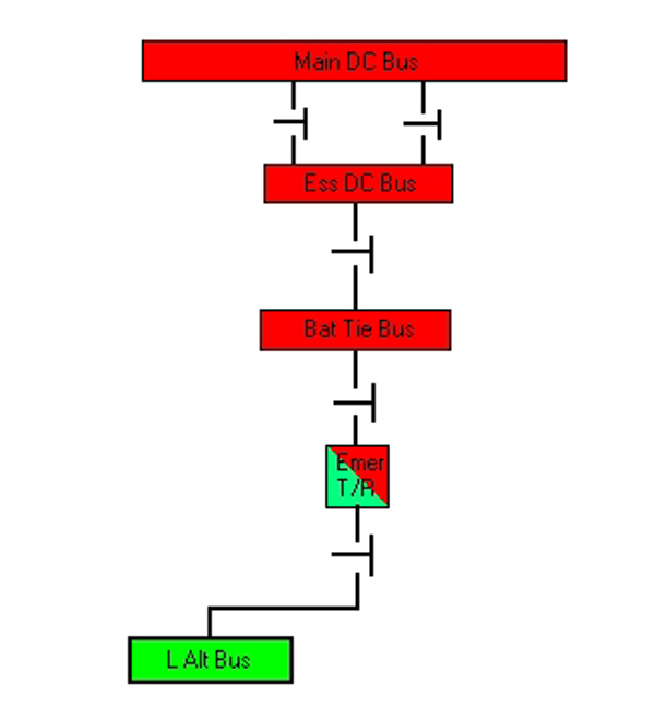
The Emergency TR is powered by the left alternator bus.
This bus should be powered if any one of the three alternators is operating.
The emergency TR can power the ESS DC bus, and both the MAIN and ESS DC busses
as desired. When the airplane is on the ground without the engines
running, the ESS TR powers the DC system. This is normal.
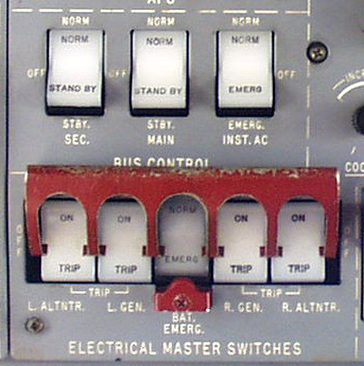
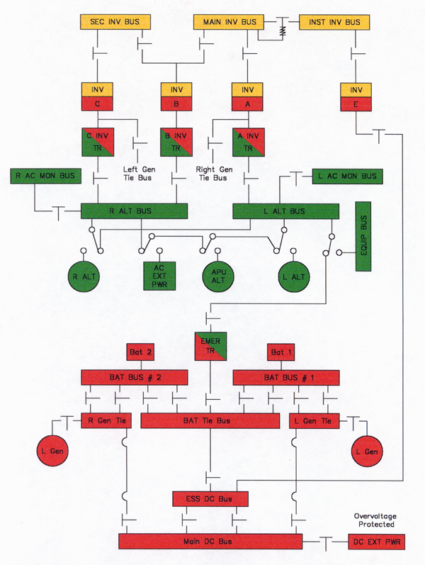
Constant Frequency AC System
The constant frequency AC system is controlled by the
switches below. Each AC bus has it's own 3 position switch. Normal,
Off, and Standby or Emerg. are the switch positions. With all three
switches in NORM, the A inverter powers the Main and INST Inverter Busses,
the C inverter powers the Secondary INV bus, and the B inverter powers nothing.
As long as the A or B inverter is powering the Main Inv. Bus, the Main and
Inst AC busses can almost be considered one bus, as they are connected.
This remains so as long as either the A or B inverter is powering it.
If, however, the E inverter is powering the Emergency Instrument Bus, the
relay between the two busses opens and the E inverter powers ONLY
the Instrement Inverter Bus. If the main or secondary inverter bus
switch is selected to standby, the B inverter powers that particular AC Bus.
The B inverter can power the Main OR the Secondary AC
bus, never both at the same time. If both the Main and Sec bus switches
are in standby, the Main gets the power.
|
|
|
|
|
|
GOInverter / Constant Frequency AC Bus Check
AC
Variable frequency AC is provided by the two ships alternators,
and on the ground only, the APU alternator. Constant frequency AC is
provided by converting the variable frequency AC to DC, with a Transformer
/ Rectifier or "TR". The then "TR's" DC output powers inverters
that produces the constant frequency AC. There are four inverters in
this system. The "E" inverter can power only the Instrument AC Bus.
The "C" Inverter powers only the Secondary AC Bus. The B inverter can
power the Main, or Main and Instrument AC Busses, OR it
can power the Secondary AC Bus, but not both. The A inverter can power
the Main AC, or the Main AC and the Instrument AC busses. The E and
B inverters are in the radio rack, and have thermal protection that will
shut them down if they overheat. The A and C inverters have overheat
warning lights, but no auto shutdown protection. If the TR's feeding
the A or the C inverters fail, those inverters may be powered by the DC system
through the use of the "Skip" switches. The inverters overheat warning
tells you that the respective inverter or the "TR" has overheated.
Switch inverters and let things cool for a minute, then if you wish to diagnose
the problem, turn the inverter back on and use the "Skip" switch. If
the fault does not recur, it was most likely the "TR", and if it does, it
was the inverter that was the problem.
|
|
|
ASC 165 - On # 001 - 155 powers inverter control circuits from ESS
DC instead of MAIN DC.
# 156 & sub are that way from the factory.
ASC 151 - On # 001 - 155 Installs INV ALT Power or "SKIP" switches.
This enables you to power
the "A" inverter from the from the R GEN tie bus, or the "C" inverter from
the L GEN tie bus.
# 156 & sub are that way from the factory.
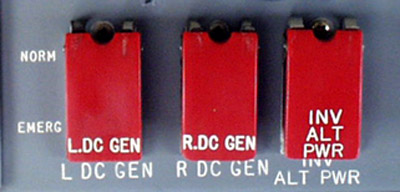
DC
DC is supplied by either or both of the DC generators, and
/ or by the Emergency "TR". The Emergency "TR" is powered by any one
of the ships alternators through the left alternator bus. The DC power
is distributed by two busses, Essential and Main. Loss of one DC generator
is not a problem, as you merely revert to "Split Buss" operation to reduce
the load on the remaining generator.. Place the TR switch to ESS, and
Bat switch to Emergency. Now, your remaining DC generator powers the
main DC Bus. The Emergency TR powers the Essential DC Bus, and keeps
the batteries charged. The Emergency TR is powered by the left AC bus.
When you select the Emergency TR, the left AC equipment bus becomes unpowered
as indicated in the previous electrical schematic.. Operation of the
Emergency TR is illustrated below. With the failure of both DC generators,
and at least one alternator on line, the Ess DC Bus can be powered by the
Emergency TR. You can also power the Main DC Bus, but be cautious not
to overload the TR or the alternator. The 300 amp TR is not installed
on all airplanes, and the alternator is limited to 53 amps for continuous
operation.
|
|
|
|
|
This is normal operation on the ground! |
The Emergency
TR can power the Ess DC Bus, or both the Ess and Main DC Bus, as selected
by the crew. The 200 Amp Emergency TR needs a bit more monitoring when
the batteries have been drained a bit. Disconnecting one battery reduces
the load on the TR by as much as 50 to 100 amps.
|
|
|
GO Battery Integrity / DC Systems Check
One Generator & One or both Alternators Operating
Split the bus! Battery switch to Emergency, TR switch to Essential. ESS DC Bus is powered by the TR, and the Main Bus is powered by the remaining generator. Load on the operating generator is reduced. The inverters are powered normally. All busses are powered except the AC equipment bus which is lost whenever the emergency TR is in use. If one alternator is inop, the AC monitor buses will be unpowered as well.
One Alternator & Both Generators Operating
No action required; The alternator busses get power from the opposite alternator bus when their own alternator fails. The AC monitor busses will not be powered. Monitor the alternator load. Windshield heat is a high draw item. In non-icing conditions, it can be shed if speed altitude and humidity permit. One of the inverters may be powered by the DC system through the use of the "Skip" switch if AC load reductin is desired.
One Generator Operating & Both Alternators Failed
Monitor the load on the remaining generator. Inst. Inv. Bus is powered by the E inverter. You will have at least the Essential DC Bus and depending on the DC load, the Main DC Bus as well.
One Alternator Operating & Both Generators Failed
Battery switch to Emergency, TR switch Essential. ESS DC Bus is powered by the TR. If the load on the generator permits, the main DC bus may be powered. The inverter system should operate normally.
Electrical Capacities
| Alternators |
58 Amps / Emergency |
| DC Generators |
|
| DC Brushless Generators ASC 285 |
Single Gen. Operation 28 Volt / 250 Amp |
| Emergency TR / Standard |
|
| Emergency TR / Optional |
|
| APU Alternator |
|
| Batteries 1 & 2 |
|
|
|
The Gulfstream II is certified for flight into known or forecast icing conditions. We will discuss the various Ice and Rain protection devices system by system. The vertical and horizontal stabilizers do not require ice protection. This was determined by flight testing during the aircraft's certification process. All of the Gulfstream's anti-ice systems are powered by the Essential DC system.
Engines
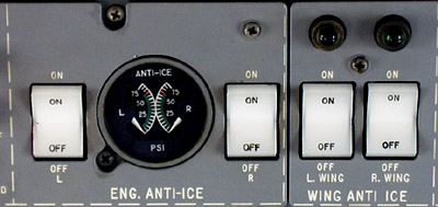
The engine inlet hub fairing, inlet guide vanes, and
the nose cowl are heated by engine bleed air in order to prevent ice formation.
The air is controlled by two engine anti-ice valves located on each engine.
They are powered by Ess DC, and fail to the closed position. These
valves are opened and closed with the "ENG. ANTI-ICE" switches. Each
valve has a separate circuit. To determine if one anti-ice valve has
failed to open, compare the engine anti-ice duct pressures. The engine EPR
pitot probes are heated electrically heated when engine anti-ice is selected
on. On aircraft with ASC 111, the EPR pitot probes are heated when
the Pitot Heat switch is on.
If the anti-ice duct pressures are the same at equal rpm,
they are OK. If they differ by 15 psi or so, and one is below 45 psi,
one valve is probably failed closed. If the pressure is more than 60
psi, a valve has more than likely failed open. These valves fail to
the closed position when Essential DC power is lost.
|
|
|
Wings
The wing leading edges are heated with engine bleed
air in order to prevent ice formation. Wing heat is controlled with
two "Wing Anti Ice" switches. Each of theses switches controls it's
respective wing anti-ice valve. This does not mean that you may heat
one wing and not the other. The bleed air ducting downstream of the
wing anti-ice valves is connected by a crossover manifold such that either
Wing Anti Ice switch being turned on heats both wings.
After activating the wing anti-ice system, the wing leading
edge begins to heat. When the respective wing temperature reaches 100
deg F, the that wing's green light above the Wing Anti Ice switches will
illuminate, indicating normal operation. The temperature is automatically
regulated. If the wing anti-ice controllers fail, and the temperature
reaches 180 deg F, a red L or R WING HT light will illuminate. You
must then turn one or both wing heat switches off as necessary to extinguish
the warning lights. The entire wing anti-ice system is useable during
emergency DC operation, as the CB's are on the Essential DC Bus.
Windshields
Rain removal is performed with hydraulically powered windshield wipers. The windshields are heated electrically. When the windshield heat switch is placed in the "ON" position, the windshields receive electrical power from the "Right Alternator Bus". This bus can be powered by either of the ships alternators, or the APU alternator if it is operating. The AC power on the Gulfstream is 3 phase. Without going into lots of detail, three phase alternators behave like three alternators, providing 3 wires, and an electrical ground. The first "Phase", or "A Phase" powers the captain's windshield. "B Phase" powers the copilot's windshield, and "Phase C" powers all the side windows as well as the "DV" window. The front windows have temperature sensors that provide the temperature controllers with the information necessary to regulate the amount of power to the windshields, thus controlling the windshield temperature. The front and DV windows have green annunciator lights that will advise you when the windshields are powered. The side and DV window temperature is controlled by thermal switches. There are no annunciator lights that address the side windows.
Pitot-Static & AOA
The pitot tubes and the angle of attack probes are electrically heated. The left form the ESS DC Bus, and the right from the Main DC Bus. When engine anti-ice is on, the EPR pitot tubes are also heated if ASC 111 is installed. Depending on the mod status of the airplane, you will have:
|
|
|
|
|
|
|
|
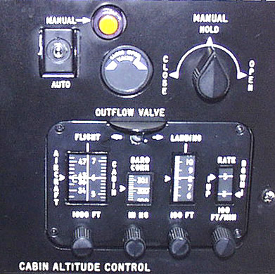
Pressurization
The cabin is pressurized with HP bleed air from the N2 compressor section of each engine. If the air-conditioning unit (boot strap) fails, emergency pressurization may be selected. This provides air from the LP or N1 compressor section of the right engine. The pressurization is regulated with one of two outflow valves. The normal outflow valve is electrically operated. It is AC powered in the "Normal" mode, and DC powered in the " manual mode. The second outflow valve is a "Safety Valve", requiring no electrical power whatsoever. This valve provides relief at maximum pressure differential, and vacuum relief, as well as a pressurization rate limiter.
During normal operation, before takeoff, you set cruise
altitude, barometric pressure, destination field elevation and cabin rate.
The system does the rest. Change the barometric pressure setting if
appropriate, and at top of descent, move the switch from "Flight" to "Landing"..
That's it! If manual mode is required, move the outflow valve as necessary
with the manual (DC electric) system. Go easy, as the valve moves quite
fast. A general announcement to the passengers may keep you from looking
like a dummy!
|
|
|
|
|
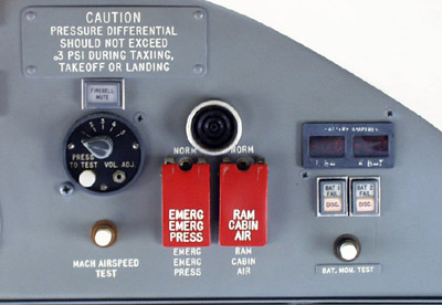
|
Emergency pressurization air comes from the LP bleed port on the right engine. Selecting RAM CABIN AIR closes the air-conditioning valve, causing the airplane to depressurize. Once the cabin has depressurized, the ram air valve opens to ventilate the cabin.
Air Conditioning
The same air that pressurizes the airplane also provides
air conditioning and heating. What a surprise we have here! The
engine bleed air is quite hot, up to 900 deg F when it comes out of
the HP port, and about 400 deg F once it passes through the precooler..
In order to cool it, there are heat exchangers in the engine pylons, and a
"Boot Strap" unit to further cool the air. The rest of the industry
calls it an "Air Cycle Machine", "ACM" or "PAC", but Gulfstream insists on
being different. In simple terms, the hot air is cooled,
compressed, cooled again, and allowed to expand, driving the cooling turbine,
further reducing the temperature of the air. This cold air is
mixed with warm air to regulate the temperature. (For more theoretical
information, see the "Glossary" included in the study guide section
of this web site. See "Air Cycle Machine") If for any reason,
like maybe smoke evacuation, you wish to depressurize the airplane and ventilate
it with ram air, you may do so by placing the "Cabin Air" switch to "RAM".
This closes the valve that allows bleed air to enter the cabin, and after
the cabin pressure leaks down, allows ambient air to ventilate, but not pressurize
the aircraft.
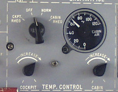
Control of the temperature is managed by a selector switch
and two rheostats on the overhead panel. The switch positions are "OFF",
"NORM", "CKPT RHEO" and "CABIN RHEO". In "NORM", the system works as
intended. The cockpit thermostat regulates the temperature in the cockpit,
and the cabin thermostat does the same for the cabin. In "CKPT
RHEO" , the cockpit thermostat and rheostat regulate the temperature of the
cockpit and cabin. In "CABIN RHEO", the cabin thermostat and rheostat
regulates the temperature of the cockpit and cabin. In "OFF", the valves
go to full cold. This may be OK in Phoenix in the summer, but as for
Bozeman Montana in the winter, or after about half an hour at cruise, you
will freeze your boss, and he will be unable to sign your paycheck.
If you must use the "OFF" position, there are two valves in the baggage compartment
that will enable you to control the temperature manually. They are
located on the left, or aft edge of the external baggage compartment door.
|
|
|
|
|
GO Entire Warning Light System
Note: I will divide these up by system
at a later date, but for now, here they are. If you are looking for a specific
one, try CTRL F, and type in what you want to find.
Back to: Airplane Driver Home Page