 |
You will find some remnants of other Gulfstream guides as
I continue to construct this one. I am using the earlier G-II
and G-III
guides as a boiler plate, so some of the photos and schematics don't
apply to the G-IV. These things will be fixed as soon as I can
get to them.
Sorry about any gaps or errors, because this guide simply
Ain't Done Yet
|
|
This guide addresses only the G IV, not the G II or G III.
The G IV is, quite similar to the late model or "AC" G III from a systems
standpoint. The electrical system is about the same except for the
emergency generator that is driven by the hydraulic system, and the minor
changes have been made to the hydraulic systems The last 10 G-III's have
the G-IV landing gear, and the very last one has the ABEX generator that
is powered by the combined hydraulic system. The engine has been
given an additional turbine wheel at the back, and a large fan in the front,
but is otherwise much the same. About 1,200 pounds more fuel
is provided. I understand that toward the middle to late part of
the flight, 2,500 lb/hr fuel flows are the norm. This is 500 lb/hr
less than the Spey powered airplanes. This increases the G IV's range
to about 4,200 nautical miles from the 3,600 mile range of the G II-B and
G III.
|
S t u d y G u i d e
|
|
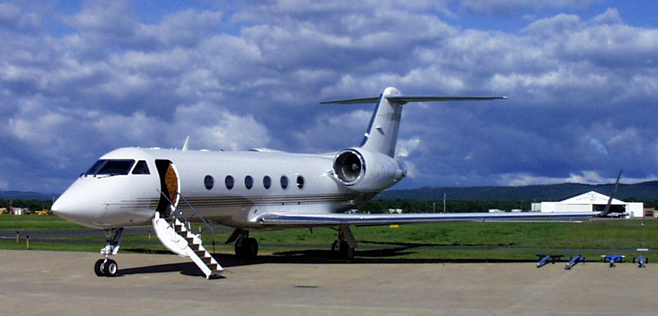
Gulfstream IV
|
|
|
|
|
|
|
|
|
|
|
|
|
|
|
|
|
|
|
|
|
|
|
|
|
|
|
|
|
|
|
|
|
|
|
Weights
| Max Ramp Weight
With SB 41040 1072 thru 1214
|
73,600 lbs 73,600 lbs
|
| Max Takeoff Weight
With SB 41040 1072 thru 1214
|
73,200 lbs 73,200 lbs
|
| Max Landing Weight
With SB 41040 1072 thru 1214
|
58,500 lbs 58,500 lbs
|
| Max Zero Fuel Weight
With SB 41040 1072 thru 1214
|
46,500 lbs 46,500 lbs
|
Typical BOW 43,500 to 44,000 lbs. # 1100 = 43,696 lbs
The above weights are maximum certificated limits. The actual maximum weights for a particular flight may vary due to the performance limitations. If the aircraft can not meet the required "Takeoff Field Length" and "Climb" limitations, (engine out climb performance), the maximum takeoff and/or landing weights are reduced such that the requirements are met. See the performance charts in the AFM for details.
Speeds
| Vmo / Mmo
35,000 ft 28,000 ft |
0.874 Mach 0.88 Mach 0.85 Mach 340 kts / 0.88 Mach |
| Va
|
206 kts |
| Vfe 10 Deg
20 Deg 39 Deg |
220 kts / 0.60 Mach 170 kts / 0.60 Mach 180 kts / 0.60 Mach |
| Vlo
Vle Emergency Extension |
250 kts / 0.60 Mach 175 kts |
| Vmcg
Vmca |
100 kts |
| Mach Trim Inop |
|
Altitudes & Misc.
| Max Alt T.O. & LDG |
|
| Max Enroute Altitude
Max Altitude Flap & Gear |
20,000 ft |
| Min Temp T.O. & LDG
Max Slush Max Water |
0.75 inch 0.50 inch |
| Max Temperature - SL to 10,000 ft
From 10,000 ft to 43,000 ft From 43,000 ft to 45,000 ft |
ISA +30 C -40 C |
| Min Temp SL - 3,500 |
|
| 3,500 - 5000 Linear |
|
| 5,000 - 10,000 |
|
| 10,000 - 35,000 Linear |
|
| Above 35,000 |
|
| Max Demonstrated X-Wind |
|
| Max Runway Slope |
|
| Max Tailwind Component T.O. & LDG |
|
| Load Factor Limit
Flaps Up Flaps Extended |
-0.0 to 2.00 G |
G IV Turn Clearance Limits
|
|
|
|
|
|
|
|
|
|
|
|
|
|
|
Tay Mk 611-8 Engine Limitations
|
|
|
|
|
|
|
|
|
|
|
|
|
|
|
|
|
|
|
|
|
|
|
|
|
|
|
|
|
|
|
|
|
|
|
|
|
|
|
|
|
|
|
|
|
|
|
|
|
|
|
|
|
|
|
|
|
|
|
|
|
|
|
|
|
|
Engine Oil System Limitations
| Min / @ Max Continuous |
|
| Min / Idle |
|
| Min To Complete Flight @ Max Cont. |
|
| Min To Complete Flight @ 92% N2 |
|
| Min To Complete Flight @ 84% N2 |
|
| Min To Complete Flight @ 76% N2 or lower |
|
| Max Oil Temp |
|
| Max Transient Oil Temp / 15 Min |
|
| Min Oil Temp for Start
Min Oil Temp Above Idle |
-30 C |
|
|
The flight controls on the G IV are cable driven with hydraulic boost.. They are powered by both the "Combined" and "Flight" hydraulic systems. Each of the systems provides 3,000 psi to the flight control servo actuators. If one system fails, the remaining system provides still provides 3,000 psi. Failure of one hydraulic system therefore, does not result in a loss of control effectiveness.
Ailerons
The hydraulically boosted ailerons provide roll control. Either or both hydraulic systems will power the ailerons. They are assisted by the two outer spoiler panels on each wing, or flight spoilers. A bungee connects the spoiler mixer and aileron on each side so that the ailerons and spoilers can be moved regardless of the status of the the other. Roll trim is provided by a trim tab located on the left aileron. The aileron trim tab is set with a manual trim wheel in the cockpit. No electric stuff here!
Elevator
The Gulfstream IV is equipped with a moveable stabilizer, elevator, and elevator trim tab system. The elevator's range of travel is from 24 degrees up to 13 degrees down. The elevator is hydraulically boosted. Elevator trim adjustments are made with the manual trim wheel in the cockpit, or electrically from the control yoke. The stabilizer is automatically adjusted when the flap setting is changed in order to compensate for changes in trim caused by flap extension and retraction. The stabilizer is moved via a gearbox in the tail. The flap gearbox is connected to the gearbox in the tail. The stabilizer position is indicated by a gauge within the flap position indicator. If the stabilizer does not position itself properly with each change in flap setting, return to the previous setting and go to the checklist. The aircraft may be landed safely with the stabilizer out of trim, however, much higher than normal control forces may be required, as the trim will not be as effective.
Mach Trim Compensator
The mach trim compensator adjust the pitch trim to
compensate for changes in the center of pressure due to changes in mach
speed. If the mach trim system fails, Mmo is reduced to 0.75 Mach.
See section 3 of the AFM. When the mach trim system and the yaw damper
have both failed, observe the most restrictive of their respective limitations,
and limit the aircraft's altitude to 41,000 feet.
Rudder
The rudder, like the rest of the flight controls
on the Gulfstream, is hydraulic. Rudder trim is provided by redefining
the neutral position with the rudder trim wheel in the cockpit. The
maximum rudder travel is 22 deg each side of center. The rudder may
be trimmed 10 units, or 7.5 deg either side of center. The yaw damper
is a full time system, powered by the "Flight" hydraulic system.
It has 3 deg of authority each side of wherever the trim and pilot input
would place the rudder. If the "Flight" hydraulic system fails, the
yaw damper is inop.
The rudder on the G IV is equipped with internal
and external load limiting systems. These systems limit the forces
applied to the rudder in order to avoid structural failure of the tail
at high speeds. This single rudder load limiter system limits hydraulic
pressure to a maximum of 2650 pounds to the rudder actuator to avoid excessive
loads on the aircraft at high speeds. The dual load limiter system
further limits the pressure to 2250 pounds. If only one of these
two systems is operable, and you have an MEL for the aircraft, you can
fly. The rudder load limiter systems generate messages in the
aircraft's warning system. If the load limiter within the rudder
actuator senses that the torque limit has been reached, a "RUDDER LIMIT"
message will appear. This is done by slowly depressing one rudder
pedal to the floor, and looking for the message to appear at full rudder
deflection. Now press the other rudder pedal to the floor, and the
message should appear again, indicating that the rudder has reached it's
mechanical stop, and the internal rudder load limiter is in fact limiting
the pressure. If you get the message in one direction but not the
other, check the rudder trim and verify that it is centered. If not,
center it and repeat the test. If the external rudder limiting system
is not operating properly, an amber "SNGL RUDDER
LIMIT" message will appear. You should get this message
until the combined hydraulic pressure is 3,000 psi.
Yaw Damper
The yaw damper is powered by the flight hydraulic system. It operates whenever the flight hydraulic system is operating. If the yaw damper fails in flight, above FL 180, maintain 220 kts or greater. At altitudes less than FL 180 maintain a minimum speed based on your fuel quantity, and if able, land with less than 9,000 lbs of fuel. If the Yaw Damper is inop prior to takeoff, a maximum fuel load of 9,000 lbs may be carried.
Yaw Damper Inop - Minimum Speed
|
|
|
|
|
|
|
|
|
|
|
|
|
|
|
|
|
|
|
|
|
|
|
|
|
|
|
|
|
|
|
|
|
|
|
|
|
|
|
Flaps
The flap system is hydraulic. Flaps may be
positioned to 0 deg, 10 deg, 20 deg, and 39 deg with the normal system.
The alternate flap control system can be used to extend or retract the
flaps to any setting between 0 deg and 39 deg. The flaps may be operated
by "Combined", "Utility", or "Aux" hydraulic systems. When the flaps
are moved, the horizontal stabilizer is repositioned via a gearbox.
|
|
|
|
|
|
|
|
|
|
|
|
|
|
|
|
|
|
|
Because it changes the angle of incidence of the
horizontal stab, it minimizes trim changes during flap extension and retraction.
Flap asymmetry protection is provided via electrical signals from the outboard
flap jackscrews. The flaps system will stop if there is 1/4 inch
or more difference in the linear travel of the flap actuators. A
torque limiter prevents damage to the system in the event of a jammed mechanism
or an attempted extension at excessive airspeed. A flap asymmetry
will not reset until it is fixed. If flap movement is arrested, it
is either loss of hydraulics, flap asymmetry, or torque limiting.
If it was torque limiting, slow the airplane down to within the limiting
speed for the flap setting you tried to get. Retract the flaps to
the previous setting, then re-extend at the proper airspeed. If this
restores flap operation, it was in fact the torque limiting system just
doing it's job. The airplane flies just fine if you stay clean until
around 200 knots. Extending the flaps at less than the limiting speeds
will minimize the unwanted pitch activity during flap extension.
In the event of unwanted flap movement, the flaps
may be stopped, and the flap selector disabled by a switch on the copilot's
lower arm ledge. With this switch activated, the flaps are moved
by the emergency flap control. Any setting between zero and full
may be selected. You still have flap asymmetry protection in the
emergency mode.
Max Flap Extension Altitude - 20,000 Feet
Max Flap Extension Speeds
|
|
|
|
|
|
|
1215 & Sub / ASC 190 |
180 kts / 0.60 Mach |
Flight Spoilers
All G IV's have six spoiler panels on the wing. They use all of the spoiler panels in flight, but only extend them to 26 deg with the speedbrake handle. Entering a turn, the spoilers on the lower wing may extend to as much as 55 degrees in conjunction with full aileron and speedbrake deflection. The Flight Spoilers / Speedbrakes are powered by both the "Combined" and "Flight" hydraulic systems. Speedbrakes may be extended with up to 20 deg of flaps. Spoiler / Speedbrakes may not be deployed in flight with the flaps more than 20 deg, or with the Landing Gear extended. The Flight Spoilers also assist in roll control, as they operate selectively with the ailerons. A bunge allows aileron movement in the event the spoiler is stuck.
Six Panel Spoiler / Speedbrake Systems
|
|
|
| Max Aileron
0 Speedbrake |
|
| 0 Aileron, Max Speedbrake |
|
| Max Aileron
Max Speedbrake |
Others 26 deg |
| Auto Ground Spoilers |
|
Ground Spoilers
The ground spoiler system uses the same spoiler panels as the flight spoilers. When actuated, the ground spoiler system extends the two inboard spoiler panels. They, in turn, cause the 4 remaining speedbrade panels to extend to 55 degrees, instead of the 26 degrees available in flight. The ground spoilers may not be armed without a successful nutcracker test after gear extension. The ground spoilers will deploy when they are armed, and both throttles are at the hard stops, and both nutcrackers indicate that the airplane is on the ground. If, the flaps are extended more than 22 degrees, when the wheels spin up to 65 kts or more, the wheel spin up can bypass the nutcracker system and deploy the ground spoilers as long as they are armed and the throttles are at idle. This means that the ground spoilers can deploy without the nutcracker system sensing that the airplane is on the ground, as long as you have left and right wheel spin up. The G-II and G-III did not have this feature. The uncertain timing of the ground spoiler extension on the earlier airplanes was enough to piss off the pope! Thank you Gulfstream for this improvement.
Nosewheel Steering
On the ground, steering is provided by
a hydraulically actuated steerable nosewheel. The nosewheel has a
mechanical limit of 82 degrees each side of center. The steering
system has stops that limit the requested angle to 80 degrees each side
of center. Unlike the earlier airplanes, the G-IV nosewheel affords
you 7 degrees of steering through the rudder pedals. This 7 degrees
of steering is introduced over a one second period starting when the nosewheel
nutcracker indicates that the nosewheel is on the ground. The
nose steering is powered by the "Combined" or the "Utility" hydraulic systems.
In the event those systems are inop, differential braking may be used for
directional control on the ground. In order to use differential
braking to steer, you must turn the nosewheel steering system off.
This is done with a red guarded switch located just forward of the tiller.
The nose steering system is disabled unless the nut crackers are in the
ground position.
The nosewheel steering is controlled with the tiller,
located to the left of the captains seat. When a steering input is
made, the tiller electrically controls the hydraulic valve that makes the
steering actuator steer the nosewheel.
Brakes
The braking system provides braking with all
4 of the main gear wheels. The main wheel rotation is automatically
slowed to 10 kts within 3 seconds after gear retraction is initiated provided
the nutcracker system senses that the aircraft is airborne. The combined
hydraulic system provides hydraulic pressure to the brakes during the gear
retraction cycle in order to stop the rotation of the main wheels.
An anti-skid system provides skid protection between 15 kts and 200 kts
during normal braking. This includes locked wheel protection if the
brakes are applied prior to touchdown. Anti-skid does, however, require
electrical power. The parking / emergency brake is powered by an
accumulator. Use of the emergency brake system can only be modulated
within the first 1/2 inch of travel. Beyond that, it usually locks
the main wheels and blows the tires. Don't play with this system.
Use only when actually needed due to the likelihood of blowing between
one and four tires.
The G-IV (excluding the G-IV SP) is equipped with
a "brake by wire" system. Some crews don't mind the system, and others
incorporate some rather color full language while describing it.
This system, as opposed to the older Gulfstream braking systems, can automatically
activate the AUX hydraulic pump in the event of combined hydraulic system
failure. It also has an anti-skid mode that pulses the brake pressure
four times per second to prevent wheel lockup if the primary anti-skid
system fails. This is referred to as the degraded performance mode.
Each of the 4 brakes has a temperature sensor.
The BTMS, or brake temperature monitoring system has a 5 position switch,
an overheat light, and a brake temperature indicator. The brake temperature
indicator will indicate the temperature of each brake as selected, or the
hottest brake when the "ALL" position is selected. A brake overheat
warning will appear when any brake temperature exceeds 400 deg C, and will
go away when all brake temperatures are below 370 deg C. Don't plan
on a successful abort at V1 if the hot brake warning has only recently
extinguished. Remember, if the brakes, due to excessive heat, cause
the temperature of the wheels to exceed 220 deg C for more than a few moments,
the fuse plugs will melt and deflate the respective tire. This can
easily happen when performing reparative full stop landings without antiquate
time for brake cooling. Keep this in mind for short legs or training
flights.
|
|
Well folks, the days of us old hardcore airplane
drivers being able to fly better than the autopilot are gone, at least
in the case of this, and a few other newer airplanes. With respect
to my brief but menaingful relationship with the G-IV, on my best day,
maybe I could come close, but the SPZ 8000 / NZ 2000 combination can just
plain out fly us human folk. The G-IV is a bit clumsy feeling compared
to it's earlier ancestors, but can be hand flown easily. By all means,
do it to stay sharp, but have no illusions. Learn to use the Flight
Management System to the fullest. It does a fine job when you figure
out how to communicate with it.
|
|
All of the Gulfstream IV aircraft are powered by
two Spey Mk 611-8 engines. These engines produce 13,850 pounds of
thrust each. The Spey Mk 611-8 is a twin spool Turbofan Engine.
The core of the 611 engine is almost identical to the older 511-8 engine
used on the earlier Gulfstream Jets.
Accessories mounted on the engine include oil pumps,
high pressure fuel pump, a hydraulic pump as well as an alternator for
each engine. These are driven by the HP or N2
section. The engine oil is cooled by fuel via a fuel / oil heat exchanger.
It heats the fuel and cools the oil. Oil pressure indications are
provided by an AC powered gauge and a DC powered low pressure light (Idiot
Light) for each engine. There is an engine oil replenishing system
installed on Gulfstream Jets. Engine oil may be serviced only on
the ground.
Variable inlet guide vanes, and farther back, a
surge bleed valve on the 7th compressor stage are installed to stabilize
the engine idle, prevent compressor stalls, and optimize the engine acceleration
characteristics. A malfunction of the surge bleed system will result
in unstable idle, poor acceleration, and compressor stall in many instances.
 |
|
|
 |
|
|
TVI
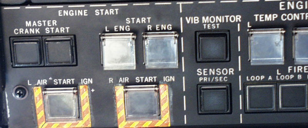
Vibration is monitored in the engine with the TVI
or Turbine Vibration Indicator system. This system allows the crew
to monitor the engine vibration. This can alert the crew of impending
malfunction or failure of the rotating engine components. Some vibration
is normal, however a change in vibration level may indicate impending doom
for the engine. See the chart below.
|
|
|
| Increase of 1.0 or more during steady state operation | Slowly close thrust lever & observe vibration during deceleration. Make an note of the maximum value. If less than 3.0 (3.5 between 67% and 74% N2), restore power and monitor engine instruments. |
| A sudden increase of 3.0 (3.5 between 67% and 74% N2) | Perform engine shutdown if situation permits. Monitor engine warning systems. |
| During start, Increase of 3.0 or more. | Abort the start. |
| During shutdown, Increase of 3.0 or more. | Record incident and have engine inspected. |
Fuel Heat
An automatic Fuel Heating system is installed on these engines. This is to prevent any ice formation in the engine fuel system. The fuel is heated by P3 bleed air, and monitored by fuel temperature gauges in the cockpit. These gauges are powered by the essential DC bus. Some fuel heating does result from the fact that the hydraulic systems have heat exchangers in the hopper tanks, however the intent of these is to cool the hydraulic fluid. The fact that the fuel is heated a small amount is not important.
Top Temp Control
A temperature control and limiting system is installed
on the Spey 511 Mk-8 engine. This system, if on, will prevent a TGT
overtemp. The temp control amplifier is powered by the 115 Volt AC
instrument Inverter Bus. The Top Temperature Control System is to
be ON except in the event the system fails.
|
|
The great thing about the APU on the Gulfstream IV
is that it will allow you to start the engines and go someplace, instead
of just sitting on the ramp. The GTPC-36-100G APU on the G-IV can
be used on the ground or in flight. On the ground it can provide
air for engine start, or air conditioning, as well as AC electrical power.
In flight, the nutcracker system prevents the APU from supplying bleed
air. Some of this AC is converted to DC with the Emergency TR.
The DC can then power the inverters, providing constant frequency AC.
So, in a round about way, the APU can power the entire airplane on the
ground.
|
|
732 Max
680 to 732 Caution
680 green
30 KVA to 22,000 feet
Linear to 15 KVA @ 30,000 feet
ASC 96 or 1156 & Sub, 30 KVA to 30,000 feet, 15 KVA @ 41,000 feet linear
Start, 15,000 feet and 250 kts max
|
|
Engines / APU
The engines and have continuous wire fire detection
loops in the engine compartments. When heated to their alarm value,
they will cause the engine fire warning system to activate. The respective
left or right ENGINE FIRE lights will illuminate. On # 173 &
Sub and aircraft with ASC 152, fire bell will sound. Press
the "Fire Bell Mute" button to cancel the bell. The fire may be extinguished
by pulling the respective fire handle, and discharging one or both of the
engine fire bottles. Their are two engine fire bottles, each containing
4.5 pounds of Bromotrifluromethane and about 600 psi of nitrogen
to disburse it. Either or both bottles may be discharged into the
selected engine.
|
|
The APU fire warning is provided by a thermal switch. The APU fire bottle is like the engine fire bottles, only smaller. It contains 2.5 pounds of the extinguishing agent, and the 600 psi nitrogen to distribute it. The APU fire bottle may be fired by lifting the guard and moving the switch. Any fire bottle that is discharged must be removed from the airplane, serviced, and reinstalled. The engine and APU fire detection systems are not part of the Master Warning System.
Note: If you get a fire warning, and perform the appropriate procedure, test the fire detection system after you believe that the fire has been extinguished. If the system won't test, the fire detection loop may have been damaged. In this case, you don't really know if the fire was actually extinguished.
Electrical
Overheat warning is provided for the generators, alternators, TR's, radio rack, and inverters. Some of the warning lights serve two items, such as a TR and an Inverter. These require some diagnosis. Refer to the checklist. The E and B inverters and the B inverter's TR have an auto shutoff feature, as they are located in the radio rack inside the airplane. When the B Inverter shuts down due to an overtemp, it also pops the breaker for the bus it was powering. If one bus caused both it's own inverter and the B Inverter to overheat, the problem is most likely on the bus.
Hydraulic
Overheat warning is provided for the Flight and Combined, systems, and the Aux hydraulic pump. These systems do not incorporate any automatic features to deal with the problem. Consult the checklist for the appropriate procedure.
Pneumatic
The wings, tail compartment, bleed air manifolds,
aft compartment, and bootstrap unit are equipped with overheat warnings.
On the ground, the bootstrap unit will shutdown automatically in the event
it overheats. In flight, the bootstrap unit will only give you a
warning, and must be shut down by the crew. Selecting either Emergency
Pressurization or Ram Air will shut down the bootstrap unit. Emergency
pressurization air is available from the LP compressor on the right engine.
The remainder of the warnings must be handled by the crew.
|
|
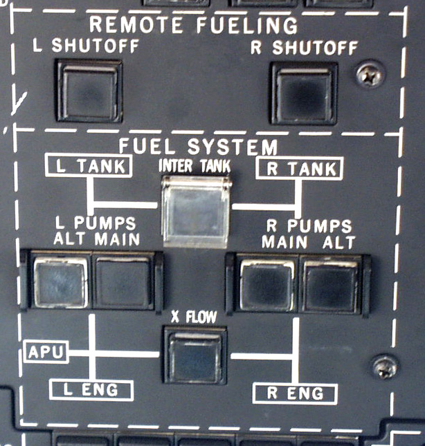
The G-IV Fuel System is simple. Fuel is stored
in the wings. Each wing tank has a "hopper" tank that is kept full
with ejector pumps and gravity. Four DC electric fuel pumps provide
fuel pressure to the engine driven fuel pumps. Warning lights will
illuminate when the hopper tank has 675 pounds of fuel or less. This
amounts to between 20 and 25 minutes at 200 knots IAS at 5000 MSL, or about
50 miles to dry tanks.
Two of the fuel pumps are designated as "Main",
and two as "Alternate". They are in fact identical. They are
located in the main wheel wells. Normally, all four pumps are on.
If one pump on a given side is turned off, the other pump can supply ample
pressure. In the event that the operating pump fails, and the failed
pump's switch is in the on position, the other pump on that side will come
on. The main fuel pumps are powered by the ESS DC bus. The
alternate fuel pumps get there power from the MAIN DC bus.
You may supply fuel to either or both engines from
either tank by opening the crossfeed valve and switching the fuel pumps
off on the side from which you do not wish to feed. An inter tank
valve is also installed, allowing fuel to gravity flow between the tanks.
G-IV Fuel Capacity
|
|
|
|
|
|
|
|
|
|
|
|
 |
|
|
The airplane burns about 5,000 lbs the first hour,
3,500 lbs the second hour, 3,300 lbs the third hour, then 3,000 lbs per
hour thereafter. Low altitude holding requires 4,000 lbs / hour fuel
flow. This gives you about 8 Hours range with 45 minutes of holding
fuel.. This will take you more than 3,200 nautical miles at
normal cruise. Use of long range cruise will result some additional
flight time. I know of flights of over 8 hours duration that landed
with legal fuel reserves. Initial cruise altitude should be FL 370
to FL 390 if you take off full. The airplane will go higher, in fact,
all the way to FL 450, but does not like it up there for the better part
of an hour. Mach 0.75 is about all it will do for a while.
The G II-B is quite an airplane. Thank God it has a bathroom.
|
|
The Gulfstream IV hydraulic system uses skydol. Hydraulic system pressure is a constant 3,000 psi.. It has two engine driven pumps, an electric aux pump, and a utility pump that is driven by the "Flight System". This "Utility Pump" is a hydraulic motor, (driven by the flight system) connected to a hydraulic pump that can pressurize the "Combined System" except the flight controls in the event that the combined system pump, or the left engine were to fail. There is no fluid transfer between the flight and combined systems. If the failure of the combined system includes loss of the fluid, the utility pump will not have any effect, as there is nothing for it to pump! The combined and flight hydraulic systems have heat exchangers located in their respective fuel hopper tanks in order to cool the hydraulic fluid. These have nothing to do with the "Fuel Heat" system which is located in each engine's nacelle.
Combined System
The "Combined System" is powered by a hydraulic
pump on the left engine. The combined system reservoir holds 5.5
gallons, 3.75 in the combined compartment, and 1.75 gallons in the aux
compartment. The total combined system fluid quantity is 15
gallons. In the case of Combined System pump, or engine failure,
the Utility Pump. The utility pump is driven by the Flight System.
The electric "Aux Pump" can power 5 items only. See the chart below.
Flight System
The "Flight" System" is powered by an engine driven
hydraulic pump located on the right engine. The flight system
It's normal operating pressure is 3,000 PSI.. The flight system
reservoir contains 1.25 gallons, and the total fluid quantity is 4.5 gallons.
Utility Pump
The Utility pump is a hydraulic pump that pressurizes
the Combined System, except the flight controls when it's own pump is not
putting out sufficient pressure for whatever reason. Operation of
the utility pump requires at least 2,000 psi flight system pressure.
The Utility pump can drive all of the combined system items except the
ailerons, elevator, rudder and flight spoilers. In the event it is
necessary to use the utility pump, those items are operated by the flight
system. If the flight system does not work, the utility pump won't
work either, as the utility pump is driven by the flight system in the
first place!
Aux System
As you can see from the table below, the aux system,
in normal operations, is used on the ground. It allows you to extend
and retract the landing gear doors during the preflight, closes the cabin
door, and provides pressure so you can set the parking brake. It
also operates the Flaps and Brakes on the ground or in flight.
|
|
|
|
System |
|
| Ailerons | Ailerons | |
| Elevator | Elevator | |
| Rudder | Rudder / Yaw Damper | |
| Flight Spoiler / Speedbrake | Flight Spoiler / Speedbrake | |
| Ground Spoilers | Ground Spoilers | |
| Left Thrust Reverser | Right Thrust Reverser | |
| ABEX Generator | Utility Pump Motor | |
|
|
||
|
|
||
| Ground Spoiler Servo | <<<--- | |
| Nose Steering | <<<--- | |
| Combined Res Pressure | <<<--- | |
| Stall Barrier | <<<--- | |
| Windshield Wipers | <<<--- | |
| <<<--- | ||
| <-Aux Pump | ||
| Landing Gear | <<<---Note: Gear on ground only! | |
| Pedal Brakes | <<<--- | |
| Flaps | <<<--- | |
| Parking Brake | <<<--- | |
| Cabin Door (Close only) | <<<--- |
Note: Use of the Aux Pump to operate the Landing
Gear on the ground applies to the landing gear doors only. The gear
doors are opened on the ground for preflight, and to keep condensation
from accumulating in the main gear doors. If you leave the airplane
in an environment where the temperature goes below freezing, any water
that may be in the main gear doors can freeze, and may interfere with landing
gear operation if it remains during gear retraction, or cause damage on
the ground if a chunk of ice falls out and hits something.
|
|
Overview
The G-IV is equipped with three "Generators".
These "Generators" are actually alternators. They produce "AC" power.
The engine driven "AC" generators produce variable frequency AC power.
The APU Generator produces 400 cycle constant frequency AC. The G-III
is equipped with two Nicad batteries for starting the APU and for emergency
power if required.
 |
|
|
Converters
Each of the two "Converters" receive variable frequency AC from their respective alternator. These converters each produce up to 23 KVA of 115 Volt 3 phase 400 cycle AC power, and up to 250 amps of 28 volt DC. This AC and DC power is routed through the "Power Distrabution Box".
Power Distribution Box
The power distribution box receives power from the left and / or right converter, or the APU alternator, and powers the single phase 400 cycle "E" inverter, the 28 volt 300 amp TRU, or transformer recitfier unit, as well as the left, right and essential AC and DC busses.
Batteries / Battery Charging
The two nicad batteries are each 20 cell, 24 volt
40 ampere hour capacity. They are controlled by their own respective
switch capsules located on the Electric Power Management Panel, or EPMP.
Each battery has it's own battery charger. The batteries are charged
quite differently than on the G-II and earlly model G-III aircraft.
These battery chargers operate between 20 volts
and 33 volts in order to provide a charging current of 38 amps for each
battery. When the charge cycle is complete, the battery ampmeter
should read zero, and the voltage should be only slightly more than 27.5
volts. If the battery voltage drops below 23 volts, the charging
cycle is repeated. The charging rate will always be 38 amps.
The time involved in the charging cycle is what will vary based on the
state of the batteries at the time the charging cycle is initiated.
The battery must be at or above 4 volts for the charging cycle to initiate.
The battery chargers may also function as Transformer-Rectifiers
to power the aux hydraulic pump. Any requirement for DC power over
and above the 50 amps each battery charger can provide is taken from the
batteries.
Emergency Transformer-Rectifier
An emergency transformer / rectifier is installed. When provided with AC power from the power distribution box, it can provide up to 300 amps of 28 volt DC power. This can power the left, right and essential DC busses. This is normal when using the APU to power the airplane on the ground. It would be considered an alternate or emergency proceedure in flight.
Electrical Power Management Panel
The "EPMP" is located on the overhead panel on the captain's side of the cockpit. (Flight Deck for those of you obcessed with political correctness). It contains the battery switches, aux power switch, left and right power switches, electrical annunciators gauges and indicators for the electrical system. It communicates with the power distribution box in order to control the electrical system, and advise the crew of what is powered by various normal and abnormal or emergency means. It looks much more complicated than it is. Most of what you do is set it up and let it do what it was designed to do. Not a whole lot of pilot intervention is required, other than maybe starting the APU and pressing the AUX power switch if necessary.
Remote Power Supply
The EPMP is equipped with a remote power supply. The remote power supply can power the EPMP with either of two power supply boards. The boards can receive power from the Essential DC Bus, or from the # 1 or # 2 battery. A third card can power the failure detection circuits and the lighting / dimmer control for the EPMP.
Overview
The G-IV is basically an "AC" airplane, much the same as the late model G-III. The G-IV has two main batteries, 40 amp/hour each for emergency power, and to start the APU. Electrical power is generated by one or both engine driven "AC Generators" or alternators producing up to 30 KVA of variable frequency AC. This variable frequency AC is routed through their own respective "Converter". The converter produces both 23 KVA of constant frequency AC, and 28 Volt DC. This electrical power is distributed to left, right and essential AC, and left right and essential DC busses. If neither of these AC generators will operate, the APU alternator may provide constant frequency AC. DC can be provided by the Emergency T/R. There is also an additional AC generator that is driven by the combined hydraulic system. In view of all this, it is quite unlikely that one would run out of electrical power in a G-IV.
Constant Frequency AC System
The constant frequency AC system is distributed through the Left Main AC bus, Right Main AC bus, and Essential AC bus. Both the left and right Main AC busses can power the Essential AC bus. They can also power each other if the Left or Right AC bus were to loose it's source of power. This is automatic, and requires no action on the part of the crew.
DC System
The DC system is distributed through the Left Main DC bus, Right Main DC bus, and Essential DC bus. Both the left and right Main DC busses can power the Essential DC bus. They can also power each other if the Left or Right DC bus were to loose it's source of power. This is automatic, and requires no action on the part of the crew.
Emergency Generator
An emergency generator is installed on the G-IV. This generator is driven by the combined hydraulic system. This is not a new idea, regardless of what Gulfstream may say. It existed on the Lockheed F-104, a 60's and 70's era fighter. This generator can produce 5 KVA of 115 Volt AC, and 50 amps of 28 volt DC power. This ain't the world, but it will give you what you need to get on the ground safely.
Avionics Inverters
Two avionics 500 VA inverters are installed. # 1 AV INV is powered by the ESS DC Bus. # 2 AV INV is powered by the Right Main DC Bus. If the # 1 AV INV fails, the backup source is the A phase of the ESS AC Bus. For the # 2 AV INV, the backup is the A phase of the right main AC Bus.
Emergency Inverter
An emergency inverter is provided. It provides single phase 800 VA AC power to the ESS AC Bus. It recieves power from the ESS DC Bus. It is intended to provide only the AC power for the items concidered essential for flight.
Battery Chargers
The batteries are charged by two chargers. Each battery has it's own charger. If the main AC busses are powered, and the battery switches are on, the chargers provide a 38 amp charge to their respective battery. This charge continues until the battery voltage reaches 33 volts, and will initiate again if the battery voltage goes below 23 volts. The battery chargers will not charge if the battery voltage is below 4 volts. The battery chargers can function as TR's. They can provide up to 50 amps each, or 100 amps total. Any additional DC power required will be supplied by the batteries.
Ground Operation
On the ground, unless the engines are running, your
choices of electrical power are, External AC, External DC or APU alternator.
External AC and the APU alternator work much the same as far as the G-IV
is concerned. The AC power is routed through different branches of
the same circuitry. It powers the main AC busses. The right
main AC bus then powers the # 2 battery charger. The Left Main AC
bus powers the # 1 battery charger and the TR unit. The TR unit then
powers the Left, Right, and Essential DC busses.
External DC powers the Left and Right Main DC busses,
and through the Left Main DC bus, powers the essential DC bus. The
essential DC bus powers the "E" inverter. The "E" inverter powers
the Essential AC Bus. The main AC busses are not powered when using
external DC power.
|
|
Electrical Capacities
| Alternators |
|
| Emergency TR |
|
| APU Alternator |
|
| Batteries 1 & 2 |
|
|
|
The Gulfstream IV is certified for flight into known or forecast icing conditions. We will discuss the various Ice and Rain protection devices system by system. The vertical and horizontal stabilizers do not require ice protection. This was determined by flight testing during the aircraft's certification process. All of the Gulfstream's anti-ice systems are powered by the Essential DC system.
Engines
The engine inlet hub fairing, inlet guide vanes,
and the nose cowl are heated by engine bleed air in order to prevent ice
formation. The air is controlled by two engine anti-ice valves located
on each engine. They are powered by Ess DC, and fail to the closed
position. These valves are opened and closed with the "ENG. ANTI-ICE"
switches. Each valve has a separate circuit. To determine if
one anti-ice valve has failed to open, compare the engine anti-ice duct
pressures. The engine EPR pitot probes are heated electrically heated when
engine anti-ice is selected on.
If the anti-ice duct pressures are the same at equal
rpm, they are OK. If they differ by 15 psi or so, and one is below
45 psi, one valve is probably failed closed. If the pressure is more
than 60 psi, a valve has more than likely failed open. These valves
fail to the closed position when Essential DC power is lost.
|
|
Wings
The wing leading edges are heated with engine bleed
air in order to prevent ice formation. Wing heat is controlled with
two "Wing Anti Ice" switches. Each of theses switches controls it's
respective wing anti-ice valve. This does not mean that you may heat
one wing and not the other. The bleed air ducting downstream of the
wing anti-ice valves is connected by a crossover manifold such that either
Wing Anti Ice switch being turned on heats both wings.
After activating the wing anti-ice system, the wing
leading edge begins to heat. When the respective wing temperature
reaches 100 deg F, the that wing's green light above the Wing Anti Ice
switches will illuminate, indicating normal operation. The temperature
is automatically regulated. If the wing anti-ice controllers fail,
and the temperature reaches 180 deg F, a red L or R WING HT light will
illuminate. You must then turn one or both wing heat switches off
as necessary to extinguish the warning lights. The entire wing anti-ice
system is useable during emergency DC operation, as the CB's are on the
Essential DC Bus.
Windshields
Rain removal is performed with hydraulically powered windshield wipers. The windshields are heated electrically. When the windshield heat switch is placed in the "ON" position, the windshields receive electrical power from the "Right Alternator Bus". This bus can be powered by either of the ships alternators, or the APU alternator if it is operating. The AC power on the Gulfstream is 3 phase. Without going into lots of detail, three phase alternators behave like three alternators, providing 3 wires, and an electrical ground. The first "Phase", or "A Phase" powers the captain's windshield. "B Phase" powers the copilot's windshield, and "Phase C" powers all the side windows as well as the "DV" window. The front windows have temperature sensors that provide the temperature controllers with the information necessary to regulate the amount of power to the windshields, thus controlling the windshield temperature. The front and DV windows have green annunciator lights that will advise you when the windshields are powered. The side and DV window temperature is controlled by thermal switches. There are no annunciator lights that address the side windows.
Pitot-Static & AOA
The pitot tubes and the angle of attack probes are
electrically heated.
|
|
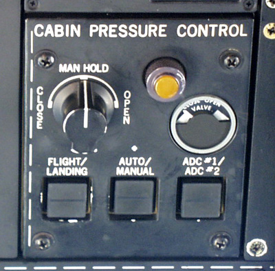
Pressurization
The cabin is pressurized with HP bleed air from the N2 compressor section of each engine. If the air-conditioning unit (boot strap) fails, emergency pressurization may be selected. This provides air from the LP or N1 compressor section of the right engine. The pressurization is regulated with one of two outflow valves. The normal outflow valve is electrically operated. It is AC powered in the "Normal" mode, and DC powered in the " manual mode. The second outflow valve is a "Safety Valve", requiring no electrical power whatsoever. This valve provides relief at maximum pressure differential, and vacuum relief, as well as a pressurization rate limiter.
During normal operation, before takeoff, you set
cruise altitude, barometric pressure, destination field elevation and cabin
rate. The system does the rest. Change the barometric pressure
setting if appropriate, and at top of descent, move the switch from "Flight"
to "Landing".. That's it! If manual mode is required, move
the outflow valve as necessary with the manual (DC electric) system.
Go easy, as the valve moves quite fast. A general announcement to
the passengers may keep you from looking like a dummy!
 |
|
|
|
|
Emergency pressurization air comes from the LP bleed port on the right engine. Selecting RAM CABIN AIR closes the air-conditioning valve, causing the airplane to depressurize. Once the cabin has depressurized, the ram air valve opens to ventilate the cabin.
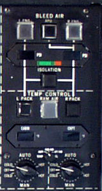
Air Conditioning
The same air that pressurizes the airplane
also provides air conditioning and heating. What a surprise we have
here! The engine bleed air is quite hot, up to 900 deg F when
it comes out of the HP port, and about 400 deg F once it passes through
the precooler.. In order to cool it, there are heat exchangers in
the engine pylons, and a "Boot Strap" unit to further cool the air.
The rest of the industry calls it an "Air Cycle Machine", "ACM" or "PAC",
but Gulfstream insists on being different. In simple
terms, the hot air is cooled, compressed, cooled again, and allowed to
expand, driving the cooling turbine, further reducing the temperature of
the air. This cold air is mixed with warm air to regulate the
temperature. (For more theoretical information, see the "Glossary"
included
in the study guide section of this web site. See "Air Cycle Machine")
If for any reason, like maybe smoke evacuation, you wish to depressurize
the airplane and ventilate it with ram air, you may do so by placing the
"Cabin Air" switch to "RAM". This closes the valve that allows bleed
air to enter the cabin, and after the cabin pressure leaks down, allows
ambient air to ventilate, but not pressurize the aircraft.
Control of the temperature is managed by a selector
switch and two rheostats on the overhead panel. The switch positions
are "OFF", "NORM", "CKPT RHEO" and "CABIN RHEO". In "NORM", the system
works as intended. The cockpit thermostat regulates the temperature
in the cockpit, and the cabin thermostat does the same for the cabin.
In "CKPT RHEO" , the cockpit thermostat and rheostat regulate the
temperature of the cockpit and cabin. In "CABIN RHEO", the cabin
thermostat and rheostat regulates the temperature of the cockpit and cabin.
In "OFF", the valves go to full cold. This may be OK in Phoenix in
the summer, but as for Bozeman Montana in the winter, or after about half
an hour at cruise, you will freeze your boss, and he will be unable to
sign your paycheck. If you must use the "OFF" position, there are
two valves in the baggage compartment that will enable you to control the
temperature manually. They are located on the left, or aft edge of
the external baggage compartment door.
 |
|
|
|
|
Back to: Airplane Driver Home Page