 |
|
|
If you see any errors or omissions, or have something usefull to add, please email me at avgroup@socal.rr.com and I will make the appropriate corrections as soon as possible. Improvements in any training material happen most rapidly with feedback from the end user. This site is for your use, let me know how I can make it better.
|
|
|
|
|
|
A word about Oxygen: Most or all of us have
heard of the Lear 35 that crashed in the North Central U.S. after flying
for several hours with a load of disceased occupants aboard. The
sad thing is that it did not have to happen. A quick preflight of
the Oxygen System would have prevented this tradgedy. Rember, pressure
trapped in the lines can cause the Oxygen Pressure Gauge to read in the
green when the Oxygen Valve is turned off. Check your mask and watch
for a drop in the pressure gauge. Twenty seconds of caution may save
your life.
|
|
| Lear |
|
| Max Ramp Weight
ECR 2173 ECR 2554 or AAK 55-82-3 ECR 2431 or AAK 55-84-6 |
20,750 lbs 21,250 lbs 21,750 lbs |
| Max Takeoff Weight
ECR 2173 ECR 2554 or AAK 55-82-3 ECR 2431 or AAK 55-84-6 |
20,500 lbs 21,500 lbs 21,500 lbs |
| Max Landing Weight
ECR 2432 or AAK 55-84-3 |
18,000 lbs |
| Max Zero Fuel Weight |
|
| Max Baggage Comp. |
|
| Typical Basic Operating Weight |
|
The above weights are maximum certificated limits. The actual maximum weights for a particular flight may vary a great deal due to performance limitations. If the aircraft can not meet the required "Takeoff Field Length" and "Climb" limitations, (engine out climb performance), the maximum takeoff and/or landing weights are reduced such that the requirements are met. See the performance charts in the AFM for details.
Speeds
|
|
|
| Vmo
At or Above 8,000 msl |
350 kts |
| Mmo
FL 370 to FL 450 FL 450 & Above Stick Puller Inop Mach Trim Inop w/o Auto Pilot |
0.79 to 0.81 M 0.79 M 0.74 M 0.74 M |
| Va |
|
| Vfe 8 Deg
20 Deg 40 Deg |
200 kts 150 kts |
| Vlo
Vle |
260 kts |
| Vsb
(Not with flaps when airborne) |
|
| Vmca
Flaps 8 / APR Operating Flaps 20 - APR Inop Flaps 20 - APR Operating |
106 kts 99 kts 101 kts |
| Vmcg |
|
| Nosewheel Steering
Primary Wheel Master |
Authority 45 kts |
| Max Tire Groundspeed |
|
| Max Alt T.O. & LDG |
|
| Max Enroute Altitude
|
41,000 ft |
| Max Alt. Flaps Ext |
|
| Min Temp T.O. & LDG |
|
| Max Temperature @ SL
|
+52 C |
| Max Tailwind T.O/ LDG |
|
| Max Runway Slope |
|
| Max Fuel Imbalance
Enroute |
500 lbs |
| Load Factor Limit
Flaps Up Flaps Extended |
+ 2.0 /- 0.0 G |
Engine Limitations
Without APR
|
|
|
|
|
|
|
|
|
|
|
|
| Takeoff
Transient |
|
|
939 C |
10 Seconds |
| Max Continuous
Max Recommended |
|
|
865 C |
No Limit |
| Max Overspeed |
103.0% to 105.0% |
105.0% |
|
5 Seconds |
With APR
|
|
|
|
|
|
|
|
|
|
|
|
| Takeoff
Transient |
|
|
929 C 939 C |
5 Minutes 10 Seconds |
| Max Continuous
Max Recommended |
|
|
865 C |
No Limit |
| Max Overspeed |
103.0% to 105.0% |
105.0% |
|
5 Seconds |
Engine Oil System Limitations
| Max Oil Temp to 30,000 ft
above 30,000 ft |
140 C 149 C |
| Min Oil Temp for Start |
|
| Max oil consumption / 25 Hours |
|
Systems
|
|
Primary Flight Controls
The ailerons, elevator and rudder on the Lear Jet
are manually actuated by the pilots. Aileron and rudder trim is achieved
with trim tabs on the rudder, and left aileron. These trim tabs are
positioned by electric motors located inside the left aileron and the rudder
it's self. Pitch trim is achieved by changing the position of the
moveable horizontal stabilizer. There are two trim motors that will
do this, a primary, and a secondary. The aileron, rudder,
and primary pitch trim are controlled with a thumb switch on the left side
of the Capt.'s and right side of the Co-Pilot's control yoke. The
secondary trim is actuated by the autopilot, and can be controlled by an
electric switch on the console in the event the primary trim fails.
All Lear Jets have autopilots, although not a very
good ones until you get to the 31, 45, 55 or 60. The ailerons and
elevator may be moved by the autopilot servos, and the rudder is equipped
with a primary and secondary yaw damper. Both yaw dampers are required
for flight although only one may be engaged at a time.
The Lear Jet has two stall warning systems.
They are the same. Both are required for flight. Angle of attack
information is given to the system by two angle of attack vanes located
on the left and right sides of the nose of the aircraft. These vanes
are heated when the pitot heat switch is on. They get hot enough
to burn you, so touch them with caution.
About 7% above a stall, the system warns you with
a flashing stall warning annunciator light, and by activating the stick
shaker. If you ignore the shaker, and continue to increase the angle
of attack, you will then get a "Nudger" that applies an intermittent foreward
push on the stick. At about 5% above a stall, the autopilot pitch
servo applies an 80 pound push on the elevator. If you do not notice
this, you deserve to crash! It is hard to ignore.
There is a "Wheel Master" button just below the
trim actuator on each pilot's yoke. It is a handy little guy.
It interrupts any elevator trim action, deactivates the stick pusher, disengages
the autopilot, and will engage the nosewheel steering if the gear is down.
The trim check very important on the Lear Jet, as the trim system on this aircraft, if not properly set can KILL you within seconds after liftoff. Excuse the lack of tact here, but it's a fact. Perform the trim check prior to takeoff.
Flaps
The flaps on the Lear are hydraulically actuated.
The flaps are controlled in one of two ways, depending on the model Lear.
Lear 55's have preselect where you place the lever in the 8 deg,
20 deg, or 40 deg position, and the flaps extend to the position requested.
If the flaps will not extend, add 30 kts to your approach speed and 30%
to your landing distance. The flaps will operate with pressure supplied
from the engine driven or the electric hydraulic pumps. There is
pressure relief valve in the flap system that will prevent damage to the
flaps if they are inadvertently extended or left down at speeds in excess
of their operating limitations.
Spoilers/Spoilerons
Lear 55's are equipped with spoilers. They
may be deployed up to Vmo / Mmo in flight only when the flaps are retracted.
On landing, they should be deployed just after touchdown. You can
have them deployed by the Auto Spoiler System, or you can just use the
switch like the earlier Lear Jets. They are hydraulically actuated,
and electrically controlled. They have two positions, fully deployed,
and stowed when operating in the "Spoiler" mode.
When the flaps are more than 25 deg extended, the
spoilers will extend on one side or the other to provide better roll control
at approach and landing speeds. In this case they are called "Spoilerons"
The spoiler on the same side as whatever aileron is deflected upward will
match the position of that aileron. This kills some of the lift on
that side, and makes low speed roll control much more effective than on
the 20 series airplanes. Spoilerons require AC power to function.
Nosewheel Steering
The nosewheel steering on the Lear is electric.
It requires both AC and DC to operate. Steering is engaged with the
wheel master switch, or by a "Steer Lock" switch on the left side and right
sides of the foreword instrument panel.. Maximum speeds for use of
nosewheel steering is either 45 knots, or 10 knots, depending on the steering
mode selected, and / or loss of wheel speed input from more than one of
the right three main wheels. See AFM for details.
Landing Gear
Like all other aircraft intended for more than one
flight, the Lear jet has a landing gear. It is extended and retracted
hydraulically, and controlled electrically. It can be extended with
high pressure nitrogen if the normal extension fails. If you extend
the Landing Gear with the nitrogen bottle, you will see three green lights,
and the two inboard gear door red lights, indicating that the gear is down,
but the inboard gear doors are still open. Do not exceed 200 knots
after alternate extension of the gear. As far as the airplane is
concerned, the gear is still in transit, at least from a limitations point
of view.
Brakes
Each main landing gear on the Lear Jet has
two wheels and tires. Each wheel has it's own hydraulic brake, with
anti-skid protection. The brakes on the left gear are controlled
by pressure applied to either of the left brake pedals, and the right brakes
work the same way from the right pedal pressure. The anti-skid system
can relieve the brake pressure on any individual wheel.
The initial brakes on the Lear 55 were woefully
inattiquite. There were situations where you could take off heavier
at high elevations with Flaps 20 deg than at Flaps 8 deg. Why?
Because you were brake energy limited. They did eventualy improve
the brakes, but the first ones were a real departure from the fine engineering
that usually exists in a Lear Jet.
If the hydraulic brake system fails, there is an
alternate brake system that will apply the brakes with high pressure nitrogen.
The same bottle is used for emergency gear extension. The emergency
brake system does not provide any anti-skid, or differential braking capability.
It is a good system, and if you use it with your brain engaged, it works
fine.
** Prior to takeoff, ALWAYS check the 3 Killer Items **
|
|
|
|
Fuel Capacity
Lear 55
|
|
|
|
|
|
|
|
|
|
|
|
|
|
|
Lear 55 ER
|
|
|
|
|
|
|
|
|
|
|
|
|
|
|
|
|
|
Fuel / Ram Air Temperature Limits
|
|
w/o AAK 55-84-1 |
AAK 55-84-1 |
|
|
|
|
|
|
|
|
|
|
|
|
|
|
|
|
|
|
|
|
|
|
|
|
The fuel system on the Lear 55 is simple, and one
of the most reliable on any aircraft. It consists of two wing
tanks, and a fuselage tank, or in the case of the 55 ER, two fuselage tanks.
The fuel feeds the engines from the wings only. left engine to left
wing, right engine to right wing. All fuel must at some time make
it's way to the wing tank if it is to be used.
The wing tanks each have an electric boost pump,
and a jet pump. The boost pump provides fuel pressure during engine
start, and when selected to transfer fuel between the wing tanks through
the crossflow manifold. The fuselage tank has two electric boost
pumps that are used to fill the tank from the wings, and to transfer the
fuel back to the wings during flight. The fuselage fuel must be transferred
by the pilots.
Wing Tanks
The wing is just a big fuel tank in the shape of an airfoil. It is divided in half by a center rib, separating it into two tanks. Relief valves are installed in the center rib (bulkhead) to prevent tank overpressure during crossflow operations. A crossflow valve is installed in a manifold connecting the left and right wing tanks. This manifold has an electric fuel boost pump on each end, allowing fuel to be transferred from one side to the other when the crossflow valve is open. There is no "Crossfeed". You can not feed, for example, the Left Engine from the Right Tank. You can, however, transfer fuel from the Right Tank to the Left Tank, thereby supplying fuel to the Left Engine. The wings may be fueled through the filler caps located just inboard of each wing tip, or via a single point refueling system if installed.
Fuselage Tank
The Fuselage Tank is installed aft of the internal baggage compartment. It is a bladder type tank. It has two electric fuel pumps that enable you to transfer the fuselage fuel to the wings, such that the fuel may finally make it to the engines. You may fill the fuselage tank by single point if installed, through it's own filler cap, or from the wings with the standby fuel pumps located in each wing center section.
You have 4 options as to how to transfer fuel from the fuselage tank to the wings:
1. Gravity Transfer - Open the transfer valves
after departure and wait. Slow but it works.
2. Normal Transfer - The left fuselage tank
pump transfers fuel into both wings.
3. Aux Transfer - The right fuselage tank
pump transfers fuel into both wings.
4. Rapid Transfer - Both fuselage tank pumps
transfer fuel into the wings.
Aft Fuselage Tank
The optional aft fuselage tank can be filled from the main fuselage tank, or with the (optional) single point refueling system. It's fuel can be transferred into the main fuselage tank. If a single point refueling system is installed, the aft fuselage fuel may be transferred directly into the wings. In the real world, this 360 pounds of fuel amounts to about 15 minutes, or a little over 100 nautical miles at cruise.
Single Point Refueling
The single point refueling system on the Lear 55 is fairly straight foreward. The single point fitting and the Fueling Control Panel are located on the right side of the fuselage just above the trailing edge of the right wing. It don't take a rocket scientist, but there are a few things to remember about this system.
1. In some of the older or unmodified airplanes, the cockpit battery switches must be on. In the newer or modified aircraft, the refueling master switch does the job from the outside.
2. Make sure the system is functioning properly prior to proceeding with the fueling. Check the auto shutoff feature with the two valves closed, and make sure that the fuel vent light remains on during the entire procedure. No light, no single point fueling. Single point fueling without the fuel vent system operating can damage the airplane.
3. If you are adding fuel, but not filling all the tanks to capacity, select "Partial" rather than full. This fills the wings first, then adds fuel to the fuselage tank(s). You want full wings if you are going to add fuel to the fuselage. Otherwise, you may find yourself with an aft center of gravity.
GO
Fuel System Photos
|
|
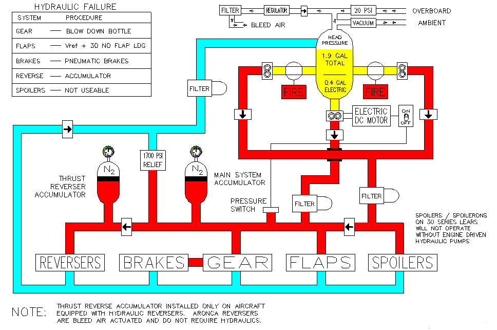
The Lear Jet hydraulic system consist of 2
engine driven, and one electric hydraulic pump, a 1.9 gallon reservoir,
an accumulator (two accumulators if Dee Howard reversers are installed)
and a couple of pressure relief valves. The fluid is 5606 therefore
if you spill some on yourself, you won't wind up looking like you and Michael
Jackson share the same dermatologist. The system operates the landing
gear, normal braking with anti-skid, the flaps, spoilers, and thrust reversers
(except aeronca) if the aircraft is so equipped.
The reservoir is pressurized by bleed air on later
models, and cabin air on earlier Lears. This is to prevent foaming.
The engine driven hydraulic pumps can only access 1.5 of the 1.9 gallons
of hydraulic fluid. The additional 0.4 gallons can be used by the
electric hydraulic pump only. It can extend the landing gear, the
flaps, provide normal braking with anti-skid, but will not operate the
spoilers. The hydraulic thrust reversers have their own accumulator,
and should be useable even with total hydraulic failure. The Aeronca
Reversers are bleed air powered, therefore do not require the hydraulic
system.
The system has two pressure relief valves, one main
system relief valve, that relieves at 1700 to 1750 psi, and one relief
valve in the flap system that relieves about 1650 psi. See "Flaps'
in the flight controls section for more details on this.
With total hydraulic system failure, blow the gear
down, approach at Vref + 30 kts, use pneumatic brakes, and plan on 1.7
to 2.0 times your normal landing distance. T/R's may work!
 |
|
|
|
|
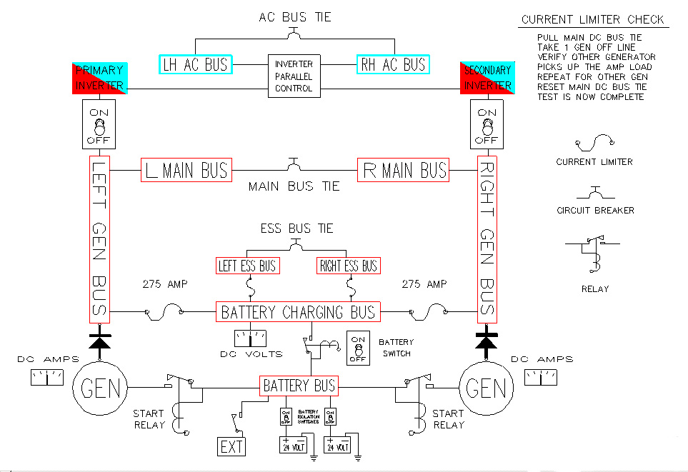
"DC" Electrical
The Lear Jet 55 DC electrical system is only slightly more complex than the earlier models. It consists of: Two batteries, usually one, but sometimes two standby batteries, two starters, two generators, several busses, some relays, current limiters, quite a few circuit breakers, and two battery switches. The main difference between the 30 series (and some later 25's) is the added "Essential" busses. They are busses that can still receive battery power with both current limiters blown.
The current limiters connect the generators to the battery
bus. The starting current goes through the start relay, and does
not pass through the current limiter. The current that recharges
the batteries does. If you blow a current limiter other than due
do an electrical short, it will probably be just after engine start when
you put the first generator online. Because the batteries are in
a discharged state, they want all of the electrons they can eat.
This is sometimes more than the current limiters can take.
 |
|
|
| Voltage |
|
| Max Amps |
|
Emergency Battery
The Emergency battery switch has three positions: OFF, STANDBY, and ON. In the ON position the emergency battery powers the small third attitude indicator, it's light, and the control circuits for the landing gear and flap systems, as well as the position lights and N1 tachometers. The three green landing gear lights are also powered by the emergency battery, and will illuminate when the gear is down and locked. The red "gear door not locked" lights are not powered by this battery. In standby, it powers just the gyro and it's light. Most of these batteries will charge in the ON and Standby positions, however, some, such as the ones in the Lear 28 must be left "ON" to be charged. Some later model aircraft may be equipped with a second standby battery. This will usually power an emergency comm radio, and whatever other devices the customer would like.
If you experience loss of all main DC bus power for any reason, remember the following:
1. Emergency battery switch to ON. Landing gear extension
will be normal
except for the loss of the red gear
door warning lights.
2. Landing gear warning horn will be inop.
3. Engine stator and nacelle lip heat are on.
4. Wing and tail anti-ice, pitot static, and angle of attack
probe heat will be inop.
5. Windshield Heat will fail in the last position selected.
6. Tank to tank fuel transfer will not be possible if crossflow
valve
was closed at time of power loss.
If crossflow valve was open, the
boost pumps will fail, making
pressure fuel transfer impossible, however,
the crossflow valve will remain
open, allowing some fuel transfer due to a
very reliable power source called
gravity.
7. The AC electrical system will be inop as it receives
it's power from the DC system.
8. The hydraulic system will be inop, except for the landing
gear and flaps, as their
control circuitry is powered by
the emergency battery when the "ON" position
is selected.
9. Nosewheel steering will be inop, as it requires
both AC and DC electrical power.
10. Anti-Skid system is inop.
These things may require some thought as to how one wishes to conduct the remainder of a flight.
Normal Operation:
Battery switches ON, before engine start,
all DC busses are powered by batteries or GPU. After engine start,
all busses are powered by the generator(s), and the batteries are recharged.
Battery Overheat
Respective battery switch OFF. This prevents
battery charging. DC busses powered by generator(s). Monitor
temp of offending battery. If your Lear does not have dual battery
switches, use the battery disconnect switch for the offending battery.
All Lear 55's have dual battery switches.
"AC" Electrical System
The Lear 55 is equipped with two inverters.
Either one can supply AC power to all items on the aircraft that require
it. They normally operate in parallel, but if one fails, the other
picks up the remaining load automatically. An AC paralleling unit
aligns the phase of the two inverters to make them work in parallel.
The AC items on the Lear include: Gyros, Autopilot,
Altitude Alert, Mach trim system, Nosewheel Steering, Engine pressure gauges,
and a few other items that vary from aircraft to aircraft.
|
|
The Lear 55 is certified for flight into known or
forecast icing conditions. Starting from the front of the airplane,
The alcohol pump provides emergency anti-ice for the left windshield.
You have 2.35 gallons of alcohol to anti ice the windshield.
This system is not frequently used, as the bleed air windshield heat usually
does the job if you operate it properly.
The pitot tubes, static ports, and angle of attack
vanes are electrically heated, controlled by the "Pitot Heat" switches
in the cockpit. The windshields are heated with engine bleed air.
If you are descending into an icing environment, remember to pre heat the
windshields about 20 minutes prior to descent. This is also the case
if you are landing anyware humid. The windshield heat wil prevent
the windshield from foging up during landing. The Aux defog system
will take care of the inside, and the windshield heat takes care of the
outside. The 55 is much better than the earlier Lear Jets in this
respect. The wing leading edges are heated with engine
bleed air. The horizontal stab leading edges are heated electrically.
These systems also need to be turned on and heated up before entering icing
conditions.
Engine nacelles and stators are heated by bleed
air. The bullet shaped nose cone for the 731 engine was heated with
bleed air as well, however almost all of the airplanes have been fitted
with the conical spinners, and require no heat, as their shape and rotation
does not allow large enough amounts of ice to form to pose any hazard to
the engine. The Tt2 and Pt2 probes in the engine inlets are electrically
heated.
|
|
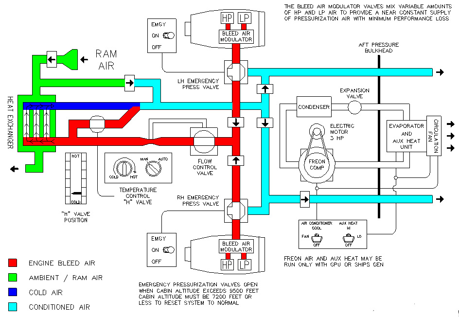
The Lear 55 is pressurized, like most airplanes,
by engine bleed air. This air comes from the HP and LP bleed sources
on the engine through a "Bleed Air Mix Valve" that regulates the bleed
air pressure by controlling the mix of LP and HP air. This air goes
through a heat exchanger in the tailcone of the airplane, and is cooled,
then goes into the cabin. Temperature is regulated by a "Damper Valve".
This valve controls the ambient airflow across the non pressurized side
of the heat exchanger. This does not provide enough cooling
for low altitude and hot weather, so a freon air conditioner is provided
for use below 18,000 feet. This freon system may not be used during
takeoff and landing, or when Stab / Wing heat is on in the Lear 55.
If it is necessary to heat the wing, you probably don't need the freon
system anyway. An Aux Heat system is installed on the Lear
55, and many earlier models. It may heat the cabin air electrically,
if you have a generator or GPU online. The cooling system switch
must be in the "Fan" position, and the Aux heat switch in high or lo.
It has various thermal protection, preventing it from burning the airplane
to the ground.
Emergency pressurization air is provided by two
emergency bleed valves that will automatically open when the cabin altitude
exceeds about 9,500 feet. These valves allow un cooled bleed air
to pressurize the cabin.
On the outflow side of things, the cabin pressure
is regulated by a main outflow valve, located at the forward end of the
pressure vessel. The automatic pressurization system requires AC
power. In the event the automatic pressurization fails, cabin pressure
may be controlled pneumatically, by the "Cherry Picker" that uses air to
move the outflow valve. Maximum differential relief at 9.7
psi, and negative pressure relief at -0.25 psi, and positive pressure
depending on the model and serial number airplane. This "Safety outflow
valve" is strictly mechanical. It requires no electrical power.
Cabin altitude limiters will close the outflow valves if the cabin altitude
reaches 11,000 ft, regardless of what else is selected.
GO
Press & Temp Control Panel Photos
 |
|
|
|
|
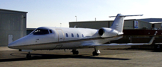
The performance of the Lear 55 won't exactly make
your eyes water if you compare it to the earlier models. It performs
much like a 35, but is much more compfortable for the passengers and crew.
It does, however, do a bit better out of the high elevation airports because
of the wing. The pilot seats are great, quite unlike the chiropractic
torture chamber seats in the earlier Lear Jets. The table below gives
approximate performance figures. Range is figured for 6 Pax and 500
lbs of baggage. If you sharpen your pencil, you can do better than
the figures below. I used 30 minutes, 1,000 lbs fuel and 160 miles
for climb and descent, and 440 kts & 1,300 lbs per hour for high speed
cruise at FL 390. You can do better, but these are figures that will
keep you out of trouble.
|
|
|
|
|
|
|
|
|
|
|
|
|
|
|
|
|
|
|
|
|
|
|
|
|
|
|
|
|
|
The use of anti ice during takeoff will reduce
your miximum climb limited weight by 1,000 to 1,500 pounds. Runway
requirement may increase by 300 or 400 feet for Nacelle Heat only, or by
as much as 1,700 feet for Nacelle & Wing heat at the higher elevations.
If the weather is so bad that you need to use the wing heat during the
takeoff roll and initial climb to 1,500 feet AGL, you will probably have
to have the airplane de-iced as well. These are "Ball Park" figures
for general information. For a particular flight, go to the AFM and
run the charts.
Note: AFM does not mean the Flight Safety or Simuflite
checklist tabular data. As handy as those tab data charts are in
day to day operations, if you must justify why you took off at a particular
weight, the FAA and NTSB will insist you use the charts in the "Aircraft
Flight Manual" to make your case. Also, in some cases, you can
takeoff a little bit heavier with the data from the AFM, as the tabular
data usually does not address wind, runway gradient, or give you the data
for your exact pressure altitude and temperature. With tab data,
you generally go to the next higher altitude and temperature to obtain
your figures. Also, interpolation of tab data is not exact, and extrapolation
is out of the question because the relationships are not linear.
Backto: Airplane DriverHome Page